Touch responsive display unit and method

a display unit and display method technology, applied in computing, instruments, device coding details, etc., can solve the problems of limited display screen size of terminal devices, difficult handling, obscure functions, etc., and achieve the effect of enhancing operability

Inactive Publication Date: 2006-02-21
HITACHI OMRON TERMINAL SOLUTIONS CORP
View PDF14 Cites 175 Cited by
  • Summary
  • Abstract
  • Description
  • Claims
  • Application Information

AI Technical Summary

Benefits of technology

[0011]Therefore, objects of the present invention are to provide a touch responsive display unit and a display method, capable of solving the foregoing

Problems solved by technology

First, regarding displaying by an operation button, a function of the operation button may not be known until it is depressed (operated). For example, there is a limit to a size of the display screen of the terminal device of the stand along type. When many operation buttons are displayed on the screen, even if a function of each operation button is displayed, the function displayed becomes obscure. Especially, for the visually impaired or the old, handling is difficult if function explanation of the operation buttons is displayed small.
Thus, even if the user thinks that he has operated, the display unit ma

Method used


Image

  • Touch responsive display unit and method
  • Touch responsive display unit and method
  • Touch responsive display unit and method

Examples


Embodiment Construction

[0046]Next, then preferred embodiments of the present invention will be described with reference to the accompanying drawings.

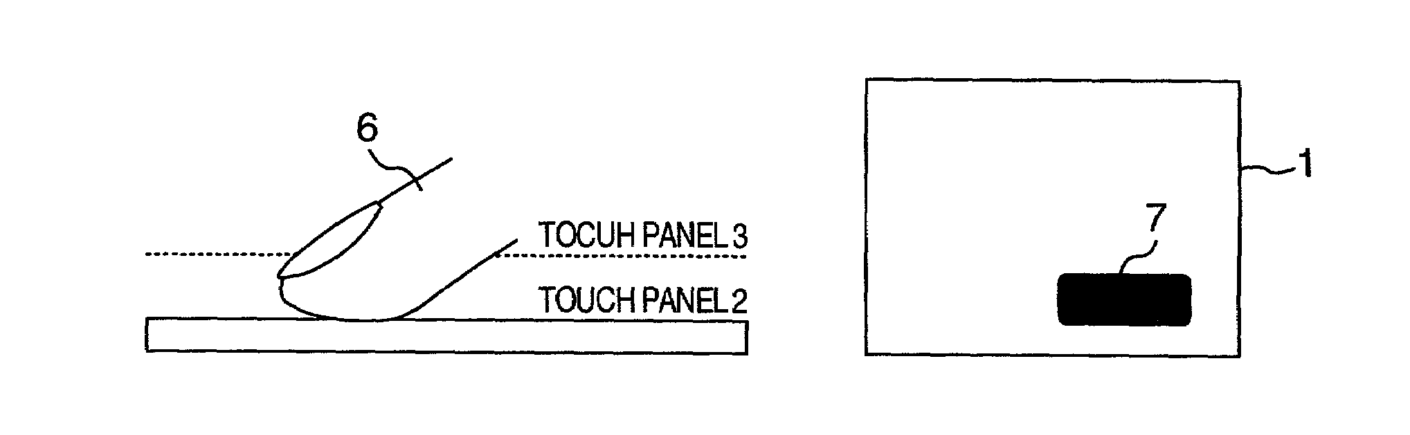
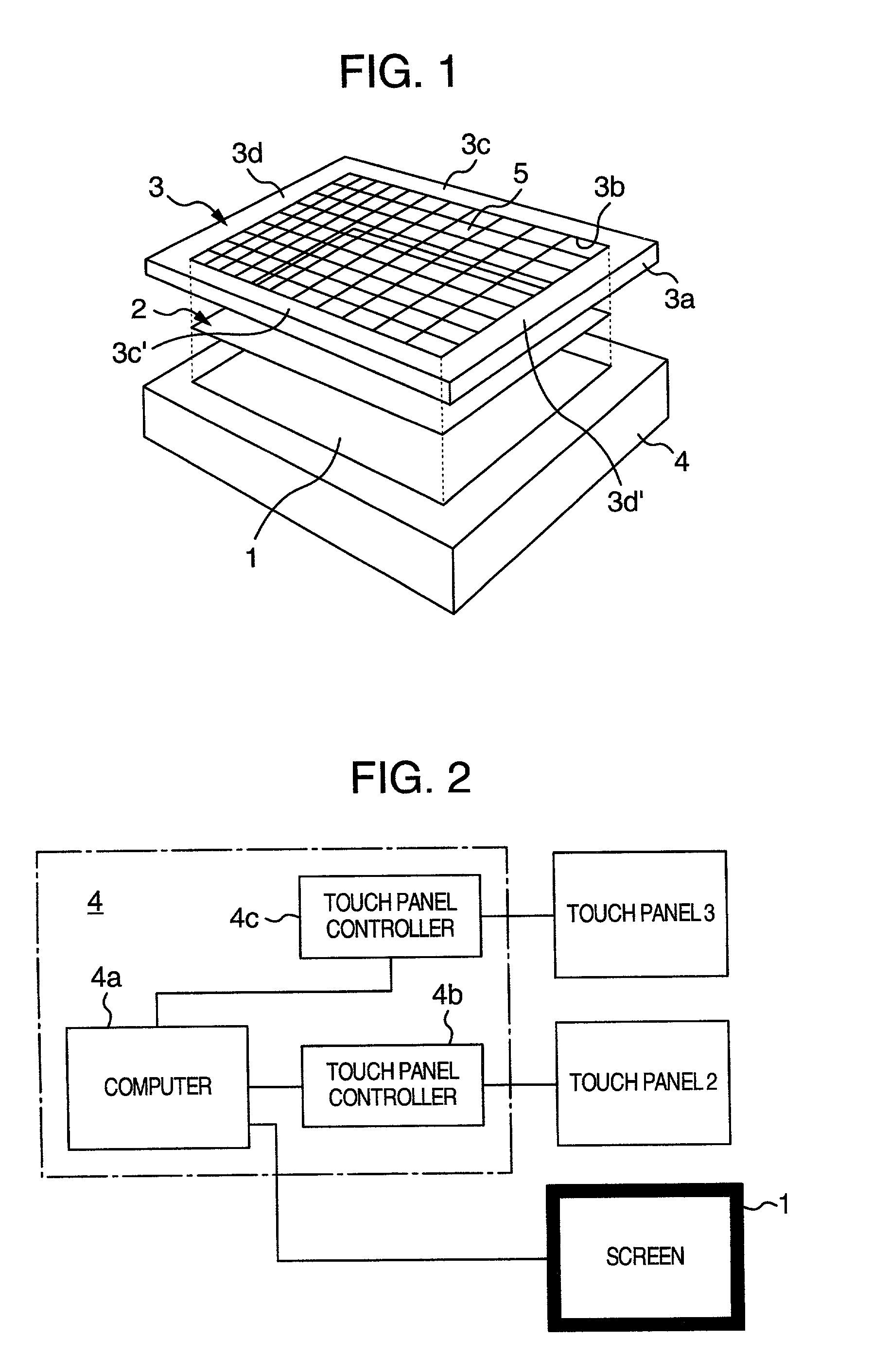
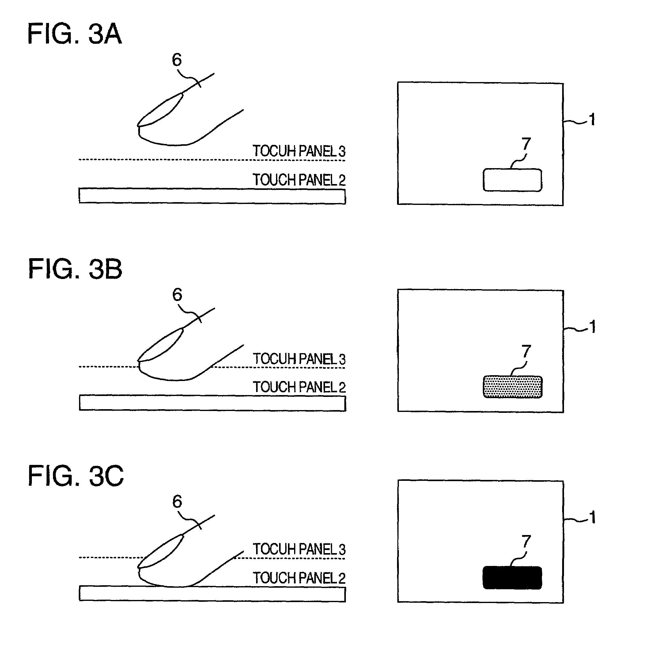
[0047]FIG. 1 is a perspective view schematically showing a configuration of a touch responsive display unit according to an embodiment of the present invention. A reference numeral 1 denotes a display screen, 2 and 3 touch panels, 3a a frame, 3b a hollow portion, 3c, 3c′, 3d and 3d′ edges, 4 a control unit, and 5 infrared rays.

[0048]In the drawing, the touch panel 2 is installed on the display screen 1 provided integrally with the control unit 4, and another touch panel 3 is installed further thereon. The touch panel 3 has the frame 3a, and a size of the hollow portion 3b inside the frame 3a is set substantially equal to that of the display screen 1. On the hollow portion 3b of the frame 3a, thin beam-shaped infrared rays 5 are radiated vertically from an inner surface of one edge 3c of the frame 3a in a horizontal direction. These infrared rays are detected ...


PUM


Abstract

As shown in FIG. 3A, a touch panel 2 is provided on a display screen 1, and a touch panel 3 using infrared rays is provided thereon. A shown in FIG. 3B, when a finger 6 touches the touch panel 3, its touching position is detected, and screen displaying is carried out on the display screen 1 according to the touching position. Then, the finger 6 is brought closer to the display screen 1. Accordingly, as shown in FIG. 3C, when the finger 6 touches the touch panel 2, its touching position is detected, and screen displaying is carried out on the display screen 1 according to the touching position. For example, in the case of an operation button 7, in FIG. 3B, displaying is carried out in a state different from that of FIG. 3A and, in FIG. 3C, displaying is carried out in another different state.

Description

BACKGROUND OF THE INVENTION[0001]The present invention relates to a touch responsive display unit and a display method used for a terminal device of a stand alone type or a portable type.[0002]In recent years, use of terminal devices has spread to various industrial fields. For example, automatic teller machines (ATM) have been installed at banks or the like, and ticket-vending machines and map guiding machines have been installed at stations, thereby enabling parts of work to be handled by the terminal devices at the banks, stations and the like. Even at stores such as fast-food restaurants, terminal devices may be used for processing orders of goods (e.g., JP-A-5-216587). Further, terminal devices for receiving contents delivered through a communication network such as Internet, terminal devices for web browsing, and the like have been realized or presented.[0003]Such a terminal device includes a display (display unit). Various operations described above can be carried out by oper...

Claims


Application Information

Patent Timeline
IPC IPC(8): G09G5/00H03M11/04G06F3/023G06F3/041G06F3/042G06F3/0487G06F3/0488
CPCG06F3/0421G06F3/04886G06F2203/04805G06F2203/04106G06F3/0482
Inventor TSUKADA, YUJINTAKANO, MASAKI
Owner HITACHI OMRON TERMINAL SOLUTIONS CORP
Why Eureka
Try Eureka