Monitored transmitter and receiver system and method for safety devices

a transmitter and receiver technology, applied in the field of door safety systems, can solve the problems of affecting the operation of the system, placing considerable physical wear and tear on the conductor, and the lack of such an important combination of features in the system disclosed in the prior ar

Inactive Publication Date: 2006-10-17
MILLER EDGE
View PDF8 Cites 38 Cited by
  • Summary
  • Abstract
  • Description
  • Claims
  • Application Information

AI Technical Summary

Benefits of technology

[0007]Further, the present invention disclosed allows for a fault signal to be generated should there be an internal failure of the door edge safety sensor such as to require communication of that fact, wirelessly, to the same controller. At the same time the system also provides for continuous fault monitoring of the wireless link between the sensor transmitter and the receiver utilized to communicate the transmitter signal to such controller. By providing a periodic signal from the transmitter to the receiver, the receiver recognizes that the communications path between the transmitter and receiver is operating. Such periodic monitoring can prevent failure of the entire system should the radio frequency link be disturbed because of equipment failure or such other environmental conditions such as electromagnetic interference created by other apparatus or equipment within the operating environment. Such a periodic signal provides a continuous status check. Depending on the battery life desired in the transmitter, such periodic status check signals should repeat on a short time basis to be assured that failure of the link during operation of the door will be noticed by the system quickly and a fault signal provided to stop operation of the door or take other action.
[0008]The system also provides a means to determine whether the door being protected is in motion, thereby signaling the transmitter to stay in continuous operation during the door movement to provide the ability for faster signaling to the receiver if a fault condition is detected. The door motion is detected using a secondary sensor such as a mercury switch or other vibration sensing switch to indicate to the transmitter that the door is moving and the transmitter should remain in an on condition through the entire operation.
[0017]The communication protocol between transmitter and receiver is simple and is designed to be as minimal as possible to speed the reaction time of the system. It is possible to support different responses for different contingencies. The communication protocol lets the receiver know exactly what the fault is, even if the end result is the same, such as a relay closure at the receiver. For example, a Maintenance-Required LED may be included which will be activated (along with the appropriate relay) to indicate a low battery situation, a tamper attempt, a secondary input sensor trip, or other fault indication.
[0019]The transmitter employs a low-inductance PCB-loop antenna. The receiver employs a Quarter Wavelength monopole antenna on a coaxial connector. Both transmitter and receiver are enclosed in boxes comprised of lightweight, high impact materials which are easily installed in the field.

Problems solved by technology

In today's environment, motor operated doors typically are expected to last ten years or more thereby placing considerable physical wear and tear on the conductors which may track the motion of the door to facilitate the connection between safety edge sensors and the controller monitoring for obstructions indicated by such sensors.
The systems disclosed in the prior art lack such an important combination of features.

Method used


Image

  • Monitored transmitter and receiver system and method for safety devices
  • Monitored transmitter and receiver system and method for safety devices
  • Monitored transmitter and receiver system and method for safety devices

Examples


Embodiment Construction

[0025]The following is a detailed description of the preferred embodiment of the Radio Frequency (“RF”) link system for an automatic door safety edge. The description is not intended to limit the scope, applicability or configuration of the invention in any way. However, the following description does provide a convenient illustration for implementing a preferred embodiment of the invention. Upon review of the following description it will occur to those skilled in the art that various changes may be made to the function and arrangement of the elements described in the preferred embodiment without departing from the spirit or scope of the invention as set forth herein and in the appended claims.

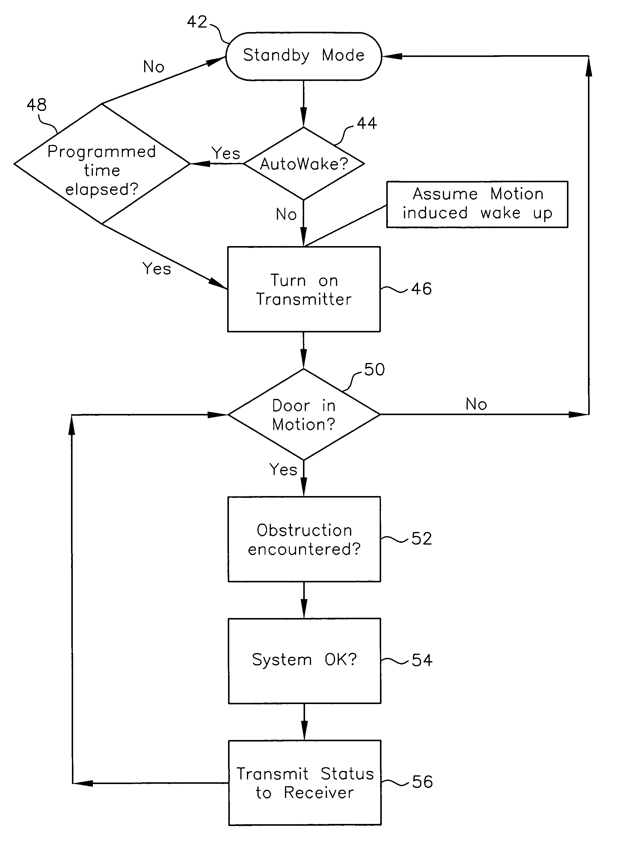
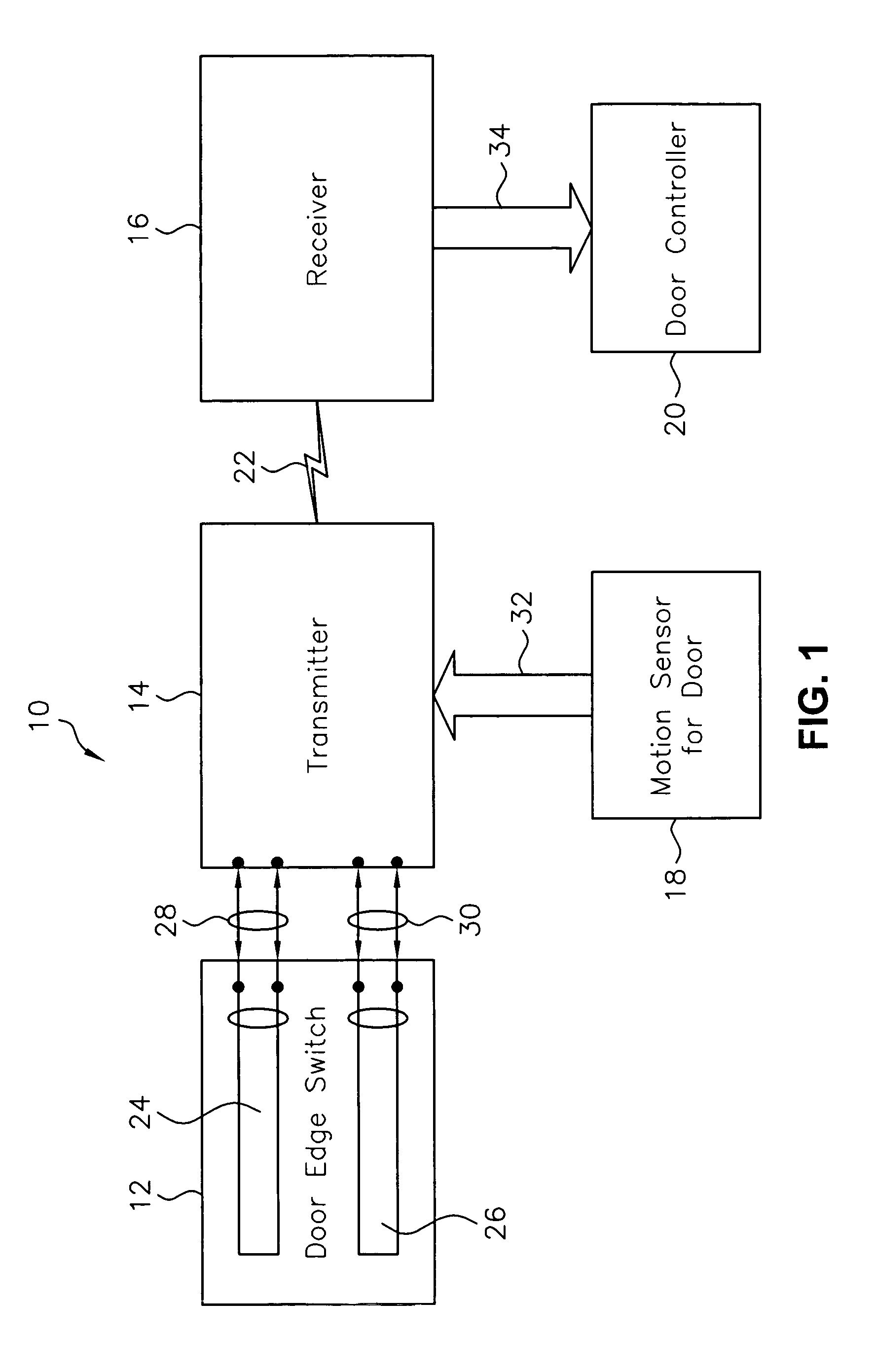
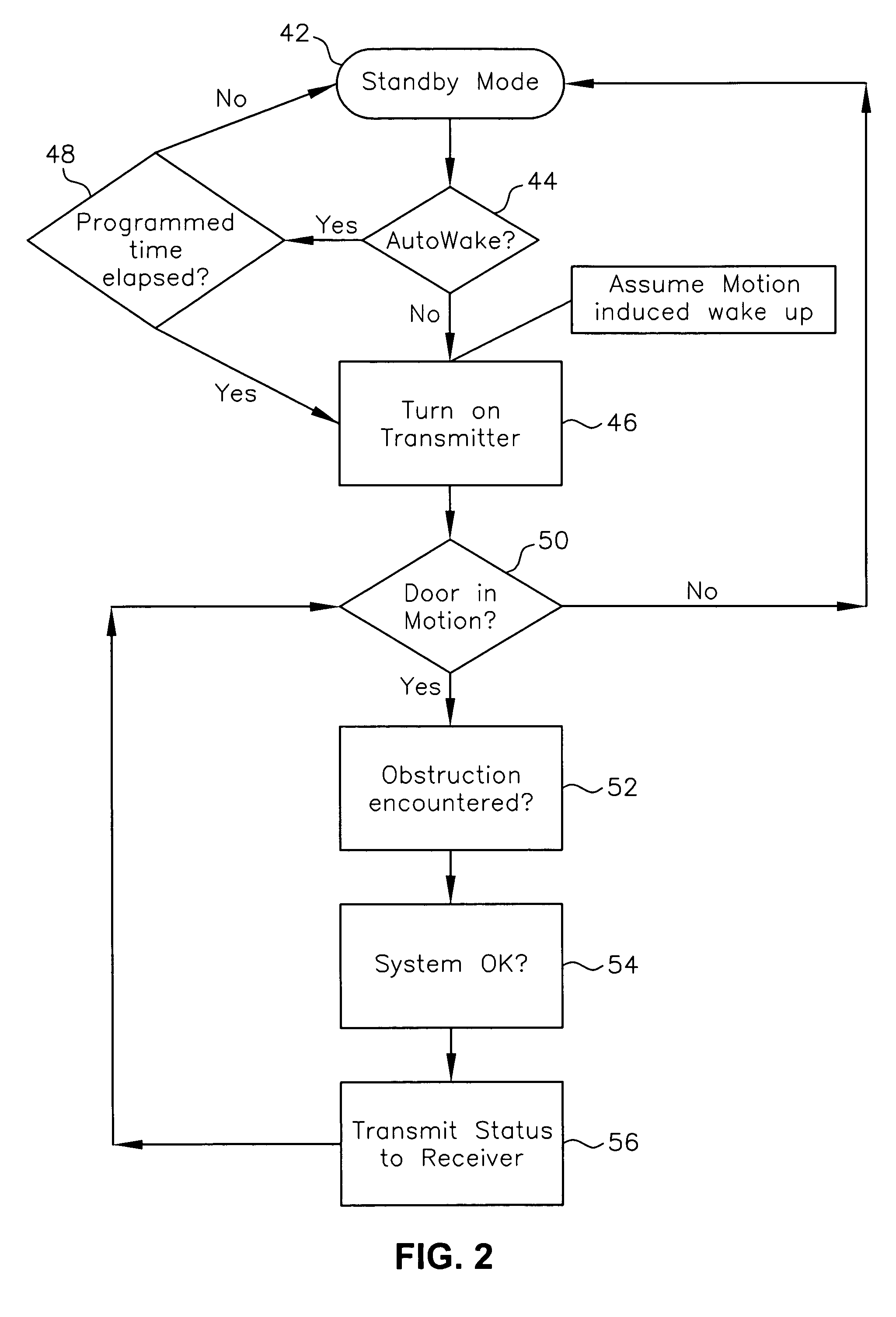
[0026]Referring now to FIG. 1, a block diagram of the entire system 10 is presented. Door edge switch 12 is a membrane type switch which utilizes a door edge safety sensor in the present invention, mounted on the lower edge of an overhead garage door or some other rolling door or movable door...


PUM


Abstract

An automatic door opening system utilizing wireless links to communicate from hazard or obstruction sensors to a controller to react to such conditions. The present invention allows the use of hazard, fault or obstruction switching devices which themselves utilize internal continuity monitoring in a wireless environment. Compressible hazard switch sensors which utilize internal, continuous conducting elements are continually monitored for breaks in such elements through continuity checks. A signal is generated from the wireless transmitter during door operation to indicate to the system that the link between the wireless transmitter and a wireless receiver is fully functioning at all times. The system can determine if an actual obstruction hazard is detected or if there is a loss of communications between the wireless transmitter and receiver link in the disclosed system while also allowing for wireless continuity checking between sensor switches utilized.

Description

CROSS REFERENCE TO RELATED APPLICATIONS[0001]The Applicants claim the benefit of their provisional application No. 60 / 464,810 filed on Apr. 23, 2003.BACKGROUND OF THE INVENTION[0002]The present invention relates generally to door systems, and more particularly to automatic door safety systems which use wireless links for sending information regarding the detection of a hazard condition or the operational status of the entire wireless system and hazard detection components of a system.[0003]Automatic door operating systems are popular in commercial or residential settings. Such doors typically include the operation of overhead door systems, elevator doors or other automatic control systems to open and close doors in various categories. Such doors also typically provide for obstruction detection to prevent the door from continuing to close when the apparatus on the door senses an obstruction in the door's path. Such obstruction sensors and obstructions switches usually include means t...

Claims


Application Information

Patent Timeline
Patent Type & Authority Patents(United States)
IPC IPC(8): G08B13/08E05F15/00G05B9/02H02P1/00
CPCG05B9/02E05F15/42E05Y2400/445E05Y2400/452E05Y2400/66E05Y2400/822E05F2015/487E05F15/00E05Y2400/44E05Y2600/46
Inventor ANDERSON, MICHAELCASTELLO, TIMOTHYLEIGH, GARYMILLER, BEARGE
Owner MILLER EDGE
Why Eureka
Try Eureka