Stem construction for rotatable valve body

a rotatable valve and stem technology, applied in the direction of valve details, valve arrangement, valve operating means/releasing devices, etc., can solve the problems of simple connection failure, user without the ability to manipulate the valve, valve stem may flex, twist or strip all together, etc., to achieve the effect of maximizing the rotational torqu

Active Publication Date: 2007-02-20
BRASSCRAFT MFG CO
View PDF16 Cites 11 Cited by
  • Summary
  • Abstract
  • Description
  • Claims
  • Application Information

AI Technical Summary

Benefits of technology

[0007]The present invention overcomes the disadvantages of the prior art by providing a valve stem construction for a rotatable valve body which maximizes the rotational torque that can be transmitted by the valve handle to the stem and valve member.
[0009]The valve stem of the present invention is provided with a unique construction to eliminate flexure or twisting of the stem while transmitting the rotational torque applied through the handle. The stem has a substantially cylindrical configuration configured to mate with the handle. The stem includes a plurality of concave splines formed longitudinally along the stem and spaced on the periphery of the stem. The splines formed on the stem are designed to mate with similarly configured splines on the valve handle such that as the stem is matingly received within the handle, the circumferentially spaced splines engage. In this manner, rotational torque applied to the handle by the user is transmitted through the splines to the valve stem for rotational operation of the valve.
[0010]The splines are configured and spaced on the periphery of the stem to provide ease of mating engagement with the handle and to minimize twisting, flexure and breakage of the stem even under increased rotational torques. In a preferred embodiment, three concave splines are formed on the stem. Rather than be equally spaced on the circumference of the stem, two of the three splines are formed closer together creating a larger gap with the third spline thereby providing orientation and alignment with the inlet and outlet. The individual spline grooves are formed with an expended chamfer at their outer end to facilitate insertion of the handle spline. An interior end of each of the splines tapers to a narrower diameter in order to create an interference fit with the handle spline. The stem also includes an axial bore for receiving a fastener used to secure the valve handle to the stem.

Problems solved by technology

Additionally, in valve assemblies which require increased rotational torque to rotate the valve member, simple connections can fail leaving the user without the ability to manipulate the valve.
Furthermore, in prior known valve members which require substantial rotational torque, the valve stem may flex, twist or strip all together.

Method used


Image

  • Stem construction for rotatable valve body
  • Stem construction for rotatable valve body
  • Stem construction for rotatable valve body

Examples


Embodiment Construction

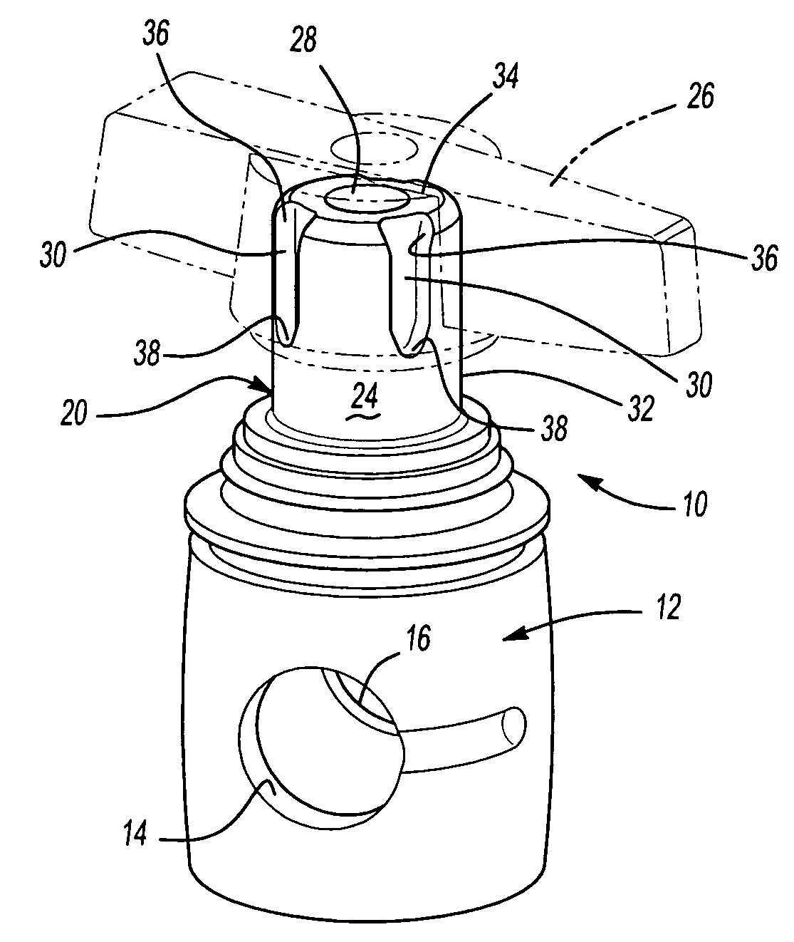
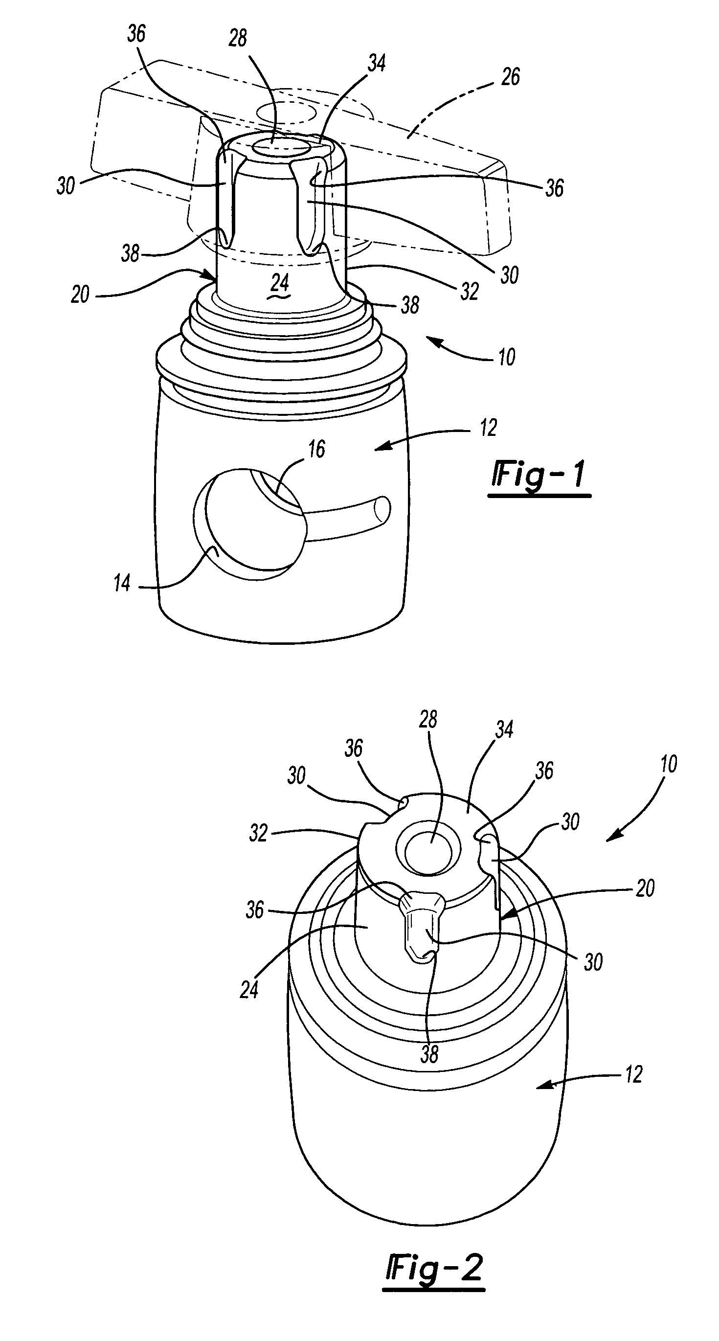
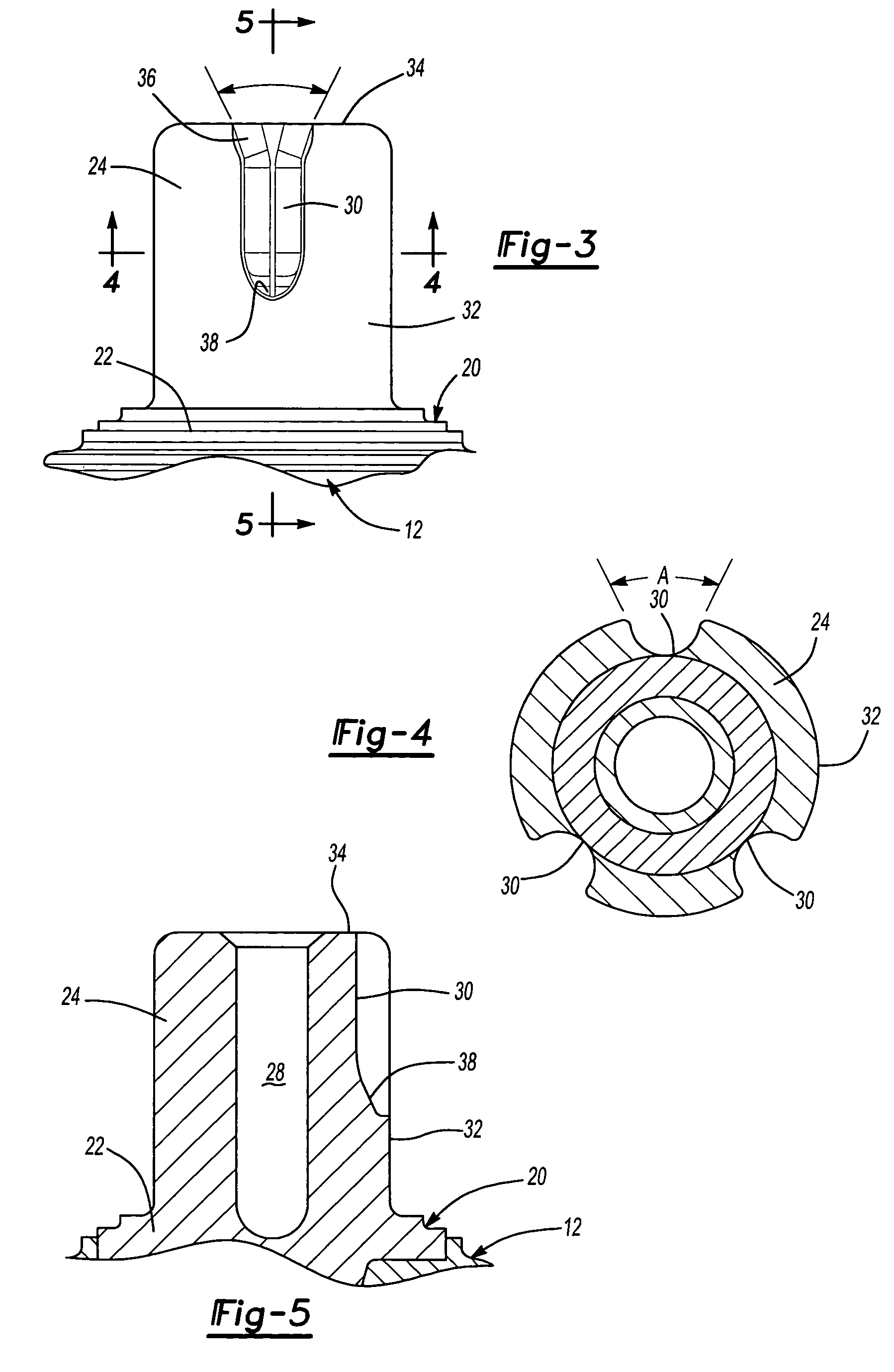
[0018]Referring first to FIGS. 1 and 2, there is shown a valve member 10 adapted to selectively control fluid flow through a valve (not shown). The valve member 10 disclosed herein is a barrel-type valve member 10 having a barrel shaped valve body 12 through which fluid flows. The valve body 12 will include a fluid inlet 14 and a fluid outlet 16 which are adapted to be aligned with inlets and outlets of the valve to control flow. Although the present invention will be described in conjunction with a barrel-type valve member, alternative configurations will also be applicable to the present invention.

[0019]Extending from the valve body 12 is a stem construction 20 used to manipulate the valve member 10 within the valve. In one embodiment of the present invention, the stem 20 and valve body 12 may be molded as a single component. In a preferred embodiment, the valve member 10 is molded in two operations allowing the valve body 12 to be molded of a softer material more conducive to sea...


PUM


Abstract

A valve stem construction for a manipulable valve member used to control fluid flow through a valve. The valve stem extends externally of the valve housing for engagement by a valve handle used to manipulate the valve member between open and closed positions. The valve is formed with a plurality of circumferentially spaced concave splines extending longitudinally on the outer surface of the valve stem. The splines are spaced so as to maximize transmission of rotational torque while minimizing flexure and twisting of the valve stem. The spacing and configuration of the individual splines also ensure a strong mating fit with the valve handle.

Description

RELATED APPLICATIONS[0001]This application claims priority from U.S. Provisional Application No. 60 / 524,195 filed on Nov. 21, 2003.BACKGROUND OF THE INVENTION[0002]I. Field of the Invention[0003]This invention relates to rotatable valves used to control fluid flow through a device and, in particular, to a unique stem configuration associated with the rotatable valve which creates a rigid connection between the valve handle and valve member.[0004]II. Description of the Prior Art[0005]Rotatable valves are traditionally used to control the flow of fluids between a fluid source and a fluid device. Such valves may simply provide for turning the flow on or off or for controlling the flow rate according to the degree of rotation. Prior known valves have included ball valves and barrel valves. The conventional valves will include a rotatable valving member disposed in a valve chamber having a fluid inlet and a fluid outlet. Similarly, the valve member will include an inlet and outlet which ...

Claims


Application Information

Patent Timeline
Patent Type & Authority Patents(United States)
IPC IPC(8): F16K5/04F16K31/60
CPCF16K31/60
Inventor TURNAU, III, WILLIAM F.TOKARZ, STEVEN J.ELDER, JACK E.WILSON, SCOTT K.
Owner BRASSCRAFT MFG CO
Why Eureka
Try Eureka