Movable console device

a console and moving technology, applied in the direction of lecterns, furniture parts, instruments, etc., can solve the problems of thereby affecting the smooth operation of the key operation, and it is difficult to ensure or establish a surface for driving the handheld-type pointing device in the console section. achieve the effect of thinning the structur

Inactive Publication Date: 2007-03-06
FUJITSU COMPONENENT LTD
View PDF10 Cites 37 Cited by
  • Summary
  • Abstract
  • Description
  • Claims
  • Application Information

AI Technical Summary

Benefits of technology

[0009]It is an object of the present invention to provide a movable console device having a rack-mount configuration and including a console section into which a keyboard and a display are incorporated, wherein the movable console device has a thinner structure able to be contained in a shelf zone having a standard unit height, and allows an operator to freely move operator's hands for operating the keyboard and to perform a smooth key-entry operation during the operating state of the console device.
[0010]It is another object of the present invention to provide a movable console device having a rack-mount configuration and including a console section into which a keyboard and a display are incorporated, wherein the movable console device has a thinner structure contained in a shelf zone having a standard unit height, and permits, when a handheld-type pointing device such as a mouse is used, a surface for driving the handheld-type pointing device to be readily ensured.
[0013]The keyboard support mechanism may fixedly hold the keyboard in the second position against a pressing force applied to an operating surface of the keyboard.

Problems solved by technology

As a result of this construction of the frame member, when the movable console device is used (i.e., when the display is disposed in the operating position), the operator's hands operating the keyboard may hit the lateral wall parts of the frame member and a smooth key-operation may be thereby obstructed.
Further, when it is desired to use a handheld-type pointing device such as a mouse, it is difficult to ensure or establish a surface for driving the handheld-type pointing device in the console section, especially in the case of such a thin structure.

Method used


Image

  • Movable console device
  • Movable console device
  • Movable console device

Examples


Embodiment Construction

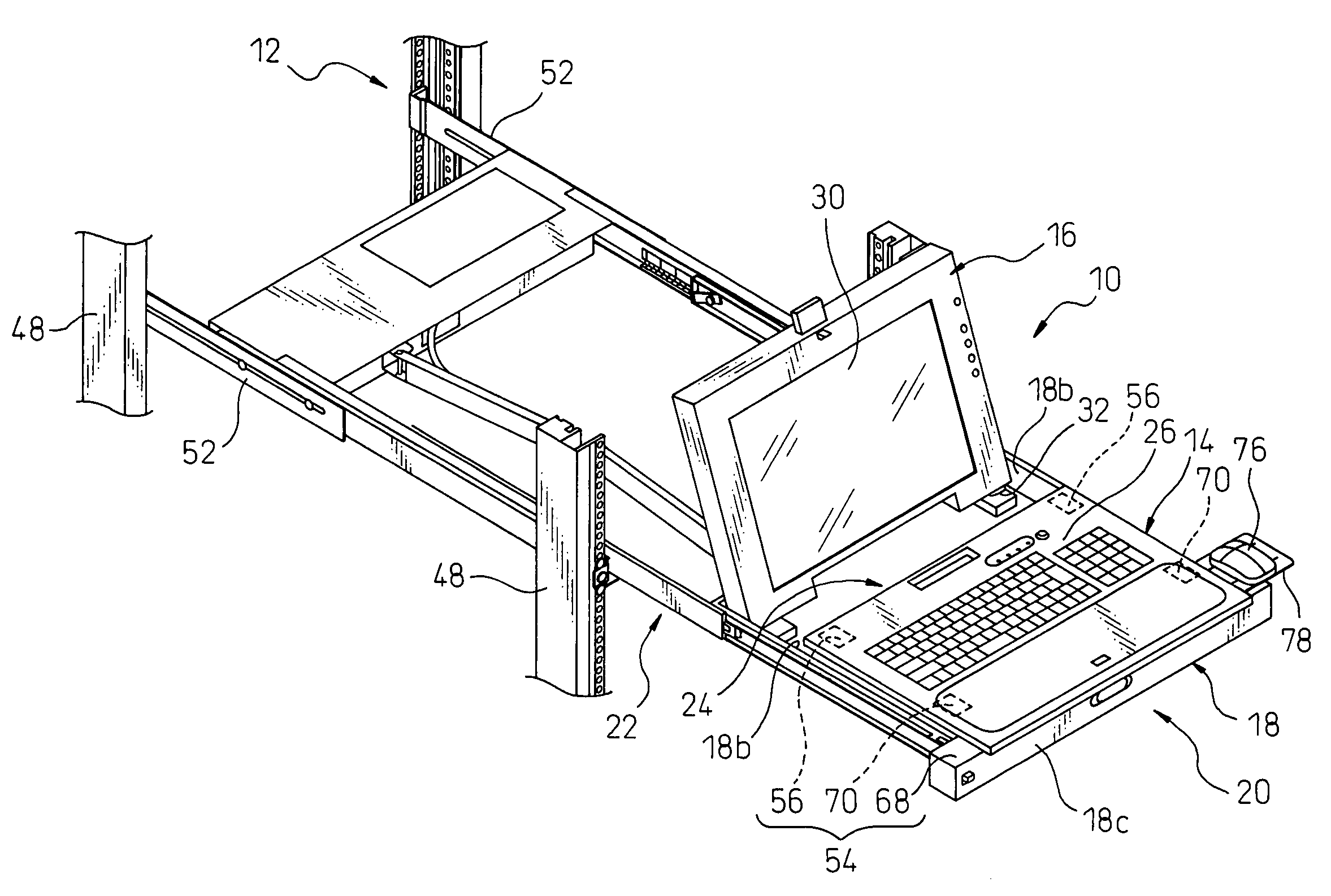
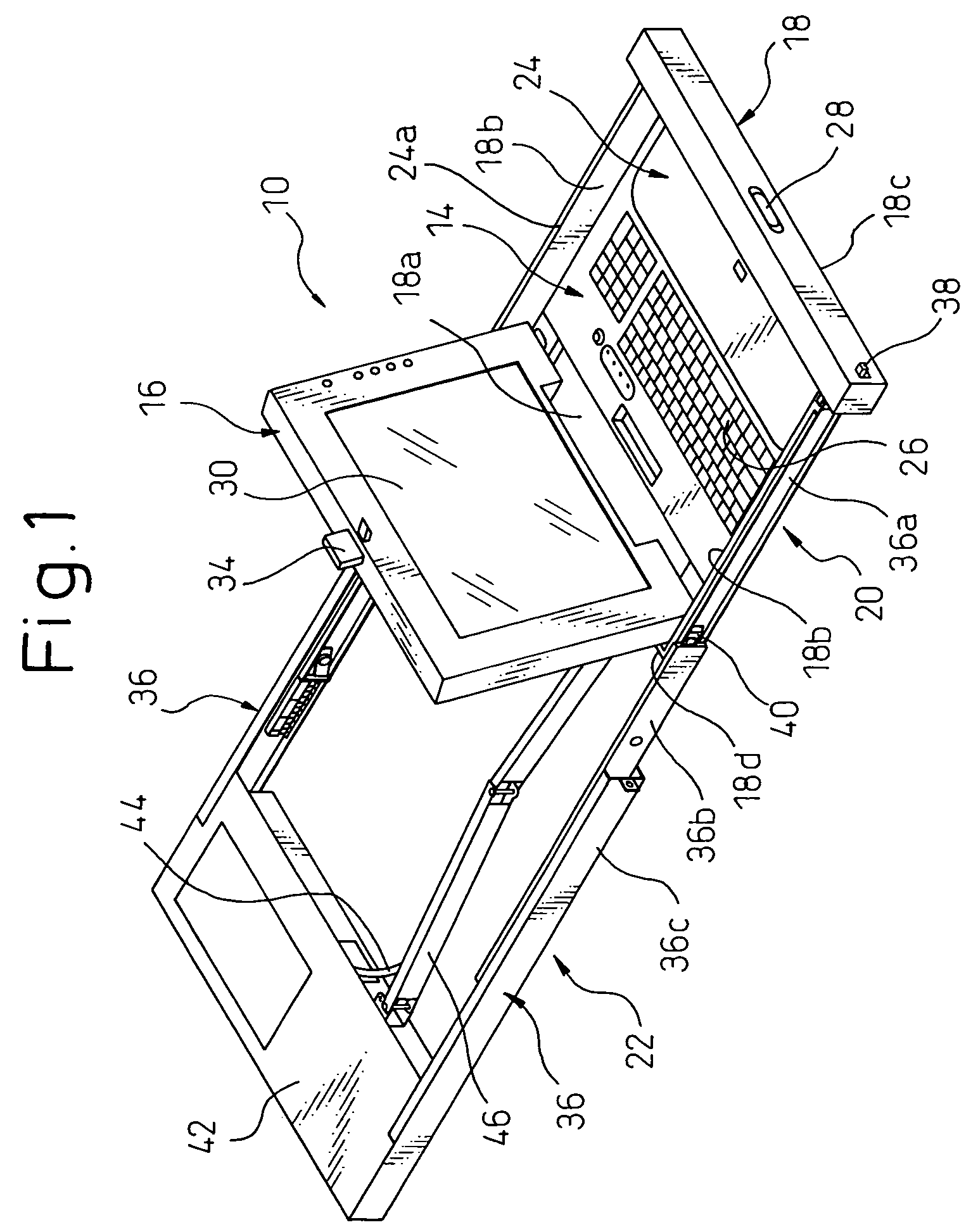
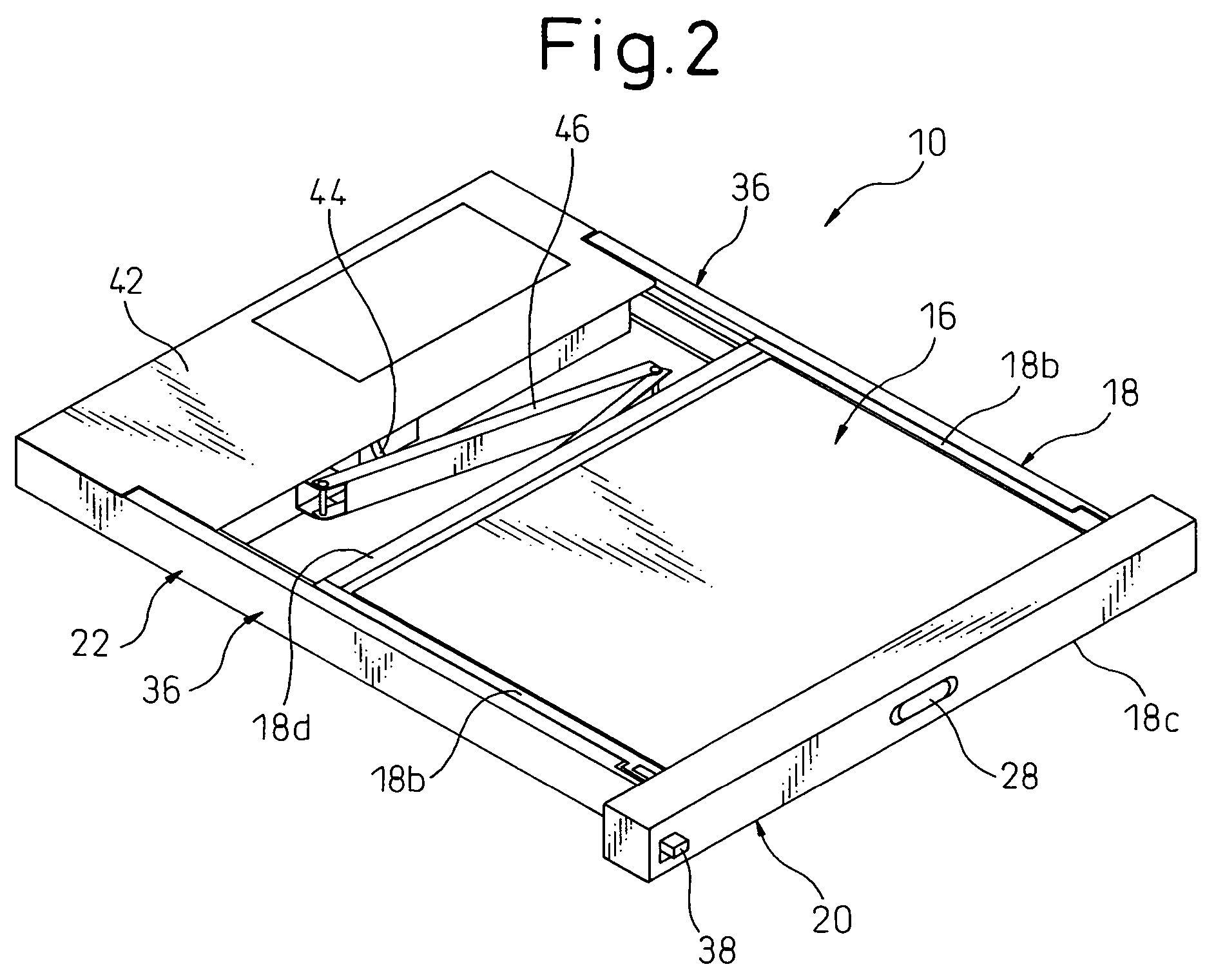
[0039]Referring to the drawings, in which the same or similar components are denoted by common reference numerals, FIG. 1 is a perspective view showing a movable console device 10 according to a first embodiment of the present invention in an unfolded or expansion state, FIG. 2 is a perspective view showing the movable console device 10 in a folded or contraction state, FIG. 3 is a perspective view showing the movable console device 10 in a state as to be mounted onto a rack structure 12, and FIG. 4 is a perspective view showing the movable console device 10 mounted onto the rack structure in an operating state.

[0040]The movable console device 10 includes a console section 20 constituted by incorporating a keyboard (or an input unit) 14 and a display (or an output unit) 16 into a common frame member 18, and a mount section 22 for mounting the console section 20 in a linearly movable manner onto a rack structure 12 prepared separately. The movable console device 10 is mounted onto th...


PUM


Abstract

A movable console device having a rack-mount configuration, including a console section and a mount section. The console section includes a keyboard and a display, and is provided with a receiving portion for receiving the keyboard and the display. The mount section is provided for movably mounting the console section onto a rack structure. A display support mechanism is provided for supporting the display on the console section to be displaceable between a non-operating position in which the display is received inside the receiving portion and an operating position in which the display extends outside the receiving portion. A keyboard support mechanism is provided for supporting the keyboard on the console section to be displaceable between a first position in which the keyboard is received inside the receiving portion and a second position different from the first position.

Description

BACKGROUND OF THE INVENTION[0001]1. Field of the Invention[0002]The present invention relates to a movable console device having a rack-mount configuration.[0003]2. Description of the Related Art[0004]In recent years, various electronic devices, such as computers, designed to be mounted for use on a rack having a predetermined dimension, have been developed. This type of electronic device, having a rack-mount configuration, is known as one which possesses superior space-saving features. In such rack-mount type electronic devices, there is known a movable console device (or a so-called console drawer) comprised of a console section including a keyboard (or an input unit) and a display (or an output unit) incorporated in a common frame member, and a mount section for mounting the console section in a linearly movable manner onto a rack structure prepared separately, wherein the movable console device is able to be taken in and out of the rack structure in a drawer-like manner (for exa...

Claims


Application Information

Patent Timeline
Patent Type & Authority Patents(United States)
IPC IPC(8): H05K7/16G06F1/16A47B21/03G06F1/18H05K7/14
CPCA47B21/0314H05K7/1494G06F1/18
Inventor SEKI, FUJIOSUGINO, HEIICHI
Owner FUJITSU COMPONENENT LTD
Why Eureka
Try Eureka