Pneumatic tire

a technology of pneumatic tires and bead parts, which is applied in the field of pneumatic tires, can solve the problems of insufficient improvement of fear of deteriorating the durability of the tire, and the inability to improve so as to achieve the effect of improving the durability of the bead portion

Inactive Publication Date: 2007-03-13
BRIDGESTONE CORP
View PDF17 Cites 3 Cited by
  • Summary
  • Abstract
  • Description
  • Claims
  • Application Information

AI Technical Summary

Benefits of technology

[0010]It is, therefore, an object of the invention to provide a pneumatic tire in which the shearing strains produced in the widthwise direction and circumferential direction of the tire during the running under loading are sufficiently decreased at the outer end position of the turnup portion of the carcass located in the bead portion even in the recent flattening of the radial tire and the repetitive retreading of the tire by properly arranging cross reinforcing layers to improve the durability of the bead portion.
[0011]It is another object of the invention to provide a pneumatic tire in which the durability of the bead portion is effectively improved by utilizing an outermost ply located in the turnup portion of the carcass while controlling the increase of the weight resulted from the arrangement of the reinforcing member.

Problems solved by technology

By such a deformation phenomenon is applied a large shearing strain to a neighborhood of an outer end of a turnup portion of a radial carcass between the carcass and rubber located therearound in the widthwise direction of the tire and hence there is a fear of deteriorating the durability of the tire.
And also, a deformation in substantially a circumferential direction of the tire is created in the sidewall portion and the bead portion corresponding to a leading part and a trailing part in a ground contact face of the tread portion, so that the shearing strain is also applied to a position of the outer end of the turnup portion of the carcass and hence there is a fear of deteriorating the durability of the tire.
In addition, the durability of the bead portion can not be sufficiently improved by the afore-mentioned means for controlling the shearing strain in the retreading operation (the retreading number also increases), and hence further improvement is desired.
In the construction shown in JP-A-11-20423, troubles may be still caused in the outer end position of the turnup portion of the carcass and there is a problem that the protecting action of the reinforcing layer to portions of the main trouble is not sufficient.
In low-section profile, large-size tires having an aspect ratio of not more than 60%, there is a serious problem that premature deterioration of new tire is caused by the trouble of the bead portion but also the retreading number decreases.

Method used


Image

  • Pneumatic tire
  • Pneumatic tire
  • Pneumatic tire

Examples


example 1

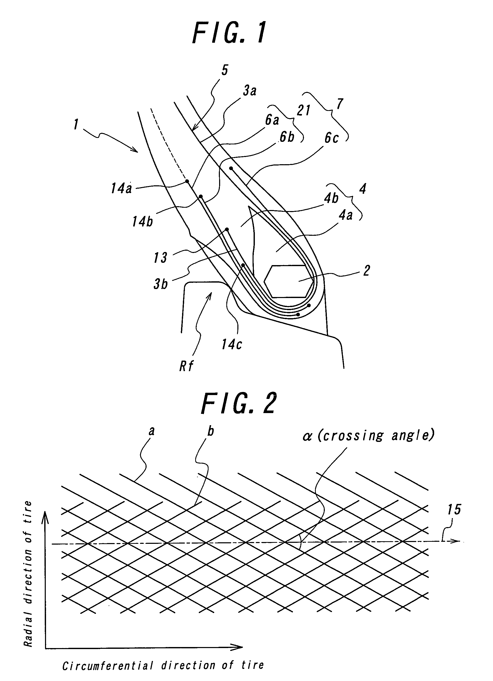
[0138]The tire of Example 1 is a pneumatic radial tire for use in truck and bus having the construction of the bead portion shown in FIG. 11 and a tire size of 285 / 60R22.5, in which a wide-width reinforcing layer (wire-reinforced layer) is arranged over a region ranging from the turnup portion of the carcass to the main body portion thereof, and a crossing angle of the cords constituting the cross cord portion is 90°, and an extending angle of the cord in the innermost reinforcing layer with respect to the circumferential direction of the tire is 45°, and an extending angle of the cord in the upper portion of the outermost ply with respect to the circumferential direction of the tire is 45°, and a bending portion is located in a position corresponding to 0.15 times a distance from a height position of a rim flange to an outer end position of the outermost ply as measured in the radial direction of the tire, and a length of the cross cord portion in the radial direction of the tire i...

example 2

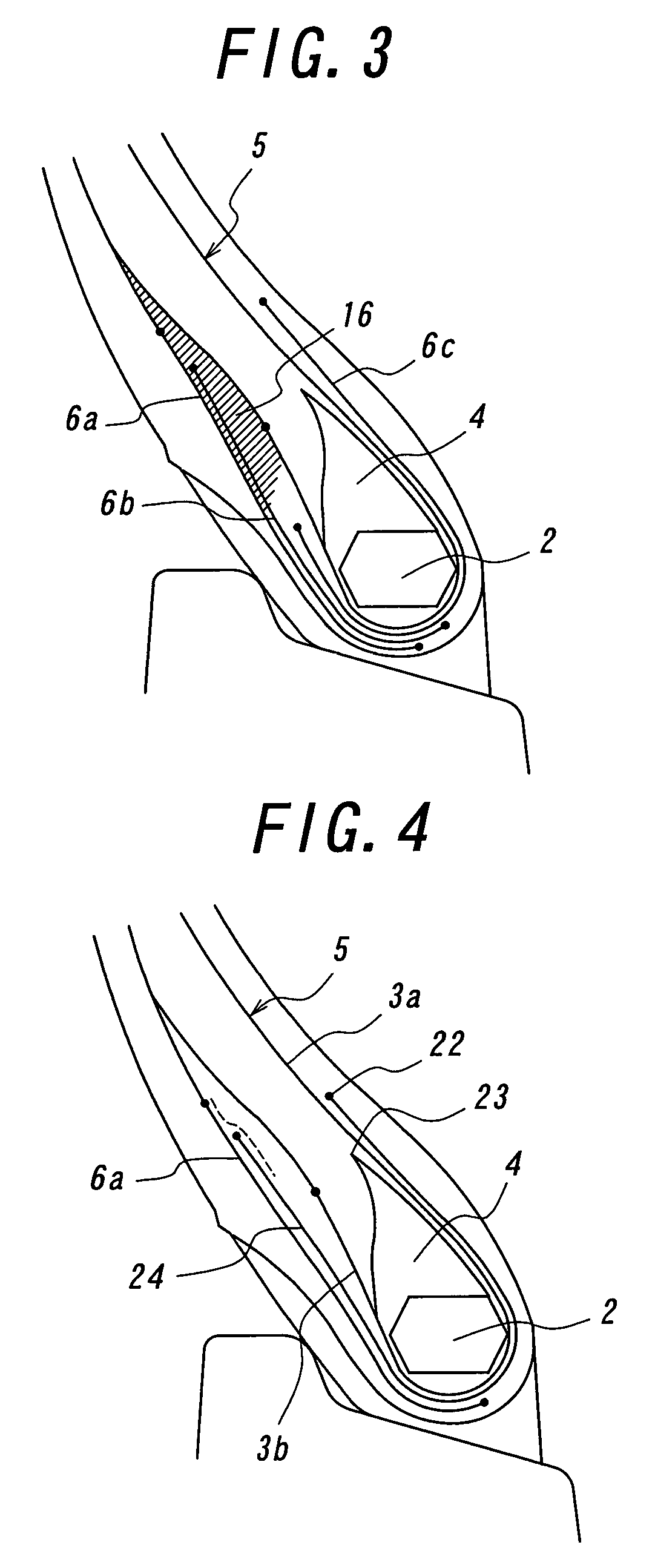
[0140]The tire of Example 2 is a tire having the construction of the bead portion shown in FIG. 16 and the same structure as in the tire of Example 1 except that a narrow-width reinforcing layer (wire-reinforced layer) is arranged only at the turnup portion of the carcass.


PUM

PropertyMeasurementUnit
crossing angleaaaaaaaaaa
angleaaaaaaaaaa

Abstract

A pneumatic tire including a radial carcass (5) of at least one carcass ply including a main body portion (3a) and a turnup portion (3b), and a reinforcing member (7) including at least two reinforcing layers. The at least two reinforcing layers (6a, 6b) are cross reinforcing layers (21) arranged so as to envelop at least the turnup portion of the radial carcass and cross cords of these layers with each other. Outer ends of the cross reinforcing layers, located outward from the turnup portion (3b) of the radial carcass in the widthwise direction of the tire, are outward from an outer end (13) of the turnup portion of the radial carcass in the radial direction of the tire. A crossing angle α between cords of adjacent cross reinforcing layers with respect to a circumferential direction (15) of the tire is more than 50° but less than 130°.

Description

TECHNICAL FIELD[0001]This invention relates to a pneumatic tire effectively improving, in particular, bead portion durability.BACKGROUND ART[0002]In the pneumatic radial tire running under loading, a phenomenon that a part of a sidewall portion located just above a tread contacting with a road surface is largely bent and also a part of a bead portion located outward from a rim flange of a wheel in a radial direction of the tire is largely deformed outward in a widthwise direction of the tire as shown in FIG. 21 repeatedly occurs every ground contact. By such a deformation phenomenon is applied a large shearing strain to a neighborhood of an outer end of a turnup portion of a radial carcass between the carcass and rubber located therearound in the widthwise direction of the tire and hence there is a fear of deteriorating the durability of the tire.[0003]And also, a deformation in substantially a circumferential direction of the tire is created in the sidewall portion and the bead por...

Claims


Application Information

Patent Timeline
Patent Type & Authority Patents(United States)
IPC IPC(8): B60C5/16B60C15/00B60C15/06
CPCB60C15/06Y10T152/10837Y10T152/10846Y10T152/10819Y10T152/10828B60C15/0607
Inventor WAKI, YOSHIYUKI
Owner BRIDGESTONE CORP
Why Eureka
Try Eureka