Balanced current lamp module and multi-lamp circuit

a lamp module and multi-lamp technology, applied in the direction of electrical equipment, instruments, light sources, etc., can solve the problems of high cost and disadvantage to manufacture, and achieve the effect of reducing the amount and cost of balanced transformers and the same luminan

Inactive Publication Date: 2008-01-15
DELTA ELECTRONICS INC
View PDF7 Cites 15 Cited by
  • Summary
  • Abstract
  • Description
  • Claims
  • Application Information

AI Technical Summary

Benefits of technology

[0010]In view of the foregoing, the present invention provides a balanced current lamp module and multi-lamp circuit, which can decrease the amount of the balanced transformers and ensure each lamp to have the same luminance.
[0014]As mentioned above, due to two ends of the other coil of the first transformer are respectively electrically connected with the first lamp and the second lamp, two ends of the other coil of the second transformer are respectively electrically connected with the third lamp and the fourth lamp, one coil of the balanced transformer is electrically connected with the first lamp, and the other coil of the balanced transformer is electrically connected with the fourth lamp, the working currents of each lamp are the same. Comparing with the prior art, a balanced current lamp module and a multi-lamp circuit according to the present invention can decrease the amount and cost of the balanced transformers, and ensure each lamp to have the same luminance.

Problems solved by technology

Thus, the cost is increased and the high cost is disadvantageous to the manufacture if the lamps are ensured to have the same luminance.

Method used


Image

  • Balanced current lamp module and multi-lamp circuit
  • Balanced current lamp module and multi-lamp circuit
  • Balanced current lamp module and multi-lamp circuit

Examples


Embodiment Construction

[0020]The present invention will be apparent from the following detailed description, which proceeds with reference to the accompanying drawings, wherein the same references relate to the same elements.

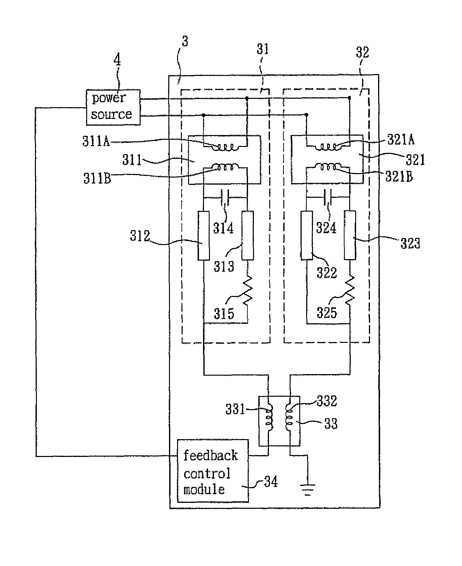
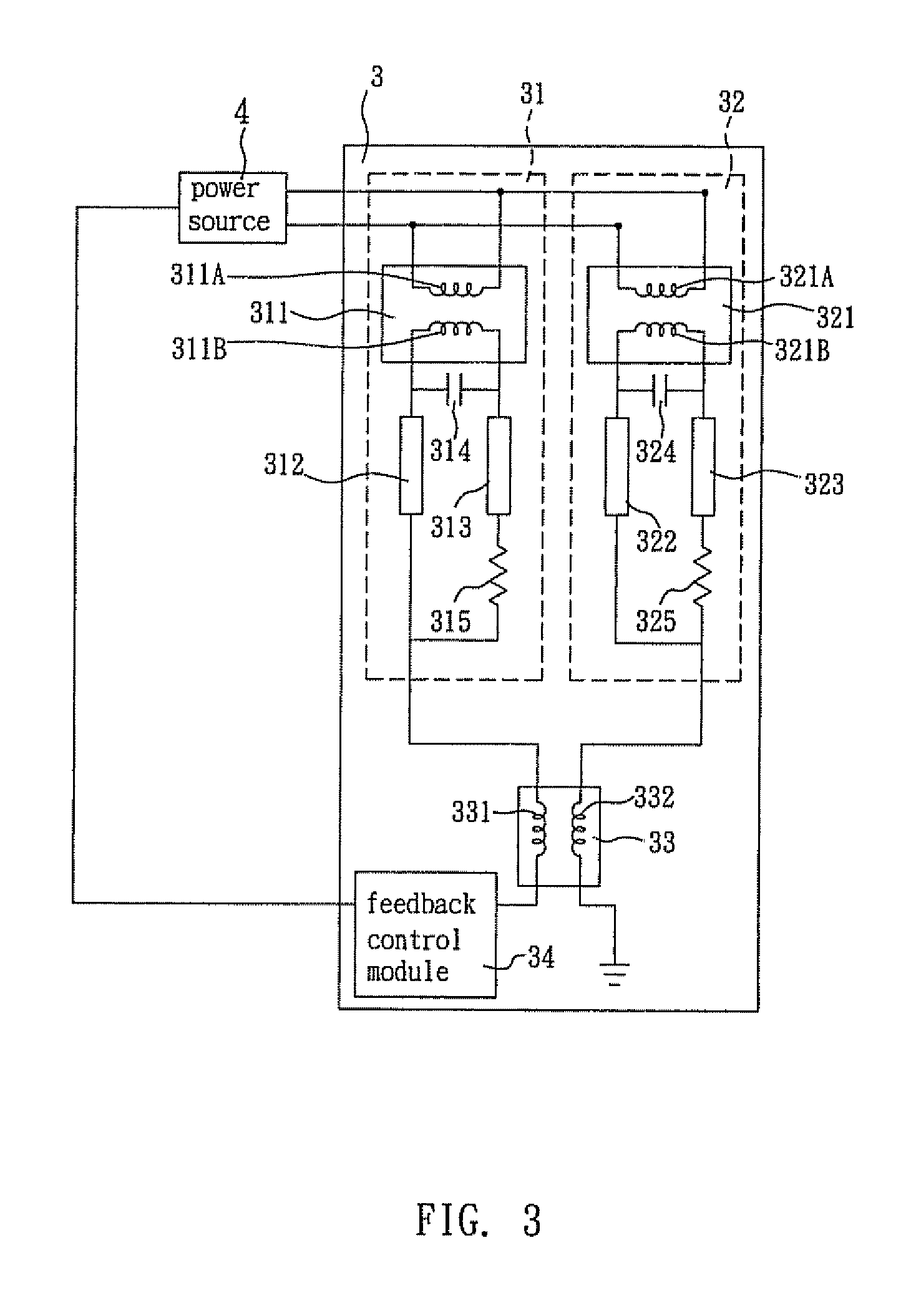
[0021]As shown in FIG. 3, a balanced current lamp module 3 according to a preferred embodiment of the present invention, which is driven by a power source 4, includes a first balanced current unit 31, a second balanced current unit 32 and a balanced transformer 33.

[0022]The first balanced current unit 31 includes a first transformer 311, a first lamp 312 and a second lamp 313. The first transformer 311 has a first coil 311A having two ends electrically connected with the power source 4, and a second coil 311B having two ends respectively electrically connected with the first lamp 312 and the second lamp 313.

[0023]The second balanced current unit 32 includes a second transformer 321, a third lamp 322 and a fourth lamp 323. The second transformer 321 has a third coil 321A having two end...


PUM


Abstract

A balanced current lamp module driven by a power source includes a first balanced current unit, a second balanced current unit and a balanced transformer. The first balanced current unit includes a first transformer, a first lamp and a second lamp. The first transformer has one coil electrically connected with the power source, and the other coil having two ends respectively electrically connected with the first lamp and the second lamp. The second balanced current unit includes a second transformer, a third lamp and a fourth lamp. The second transformer has one coil electrically connected with the power source, and the other coil having two ends respectively electrically connected with the third lamp and the fourth lamp. The balanced transformer has one coil electrically connected with the first lamp, and the other coil electrically connected with the fourth lamp.

Description

BACKGROUND OF THE INVENTION[0001]1. Field of Invention[0002]The present invention relates to a lamp module and a multi-lamp circuit, and more particularly, to a balanced current lamp module and a multi-lamp circuit.[0003]2. Related Art[0004]Because a cold cathode fluorescent lamp (CCFL) has a high luminance, the CCFL can serve as a light source and be applied to an electronic device, such as a liquid crystal display, to serve as a backlight source.[0005]FIG. 1 is a schematic view showing a driving circuit for a conventional balanced current lamp circuit. As shown in FIG. 1, a power source 11 is electrically connected with a coil 121 of a transformer 12, and two lamps 14 and 16 are respectively electrically connected with the other coil 122 of the transformer 12 through two capacitors 13 and 15. However, this connection method cannot ensure the working currents of the lamps 14 and 16 to be the same, and the luminance of the lamps 14 and 16 is thus different from each other.[0006]Furt...

Claims


Application Information

Patent Timeline
Patent Type & Authority Patents(United States)
IPC IPC(8): H05B41/24
CPCH05B41/2822
Inventor KUO, CHUN-LIANG
Owner DELTA ELECTRONICS INC
Why Eureka
Try Eureka