Vehicle deceleration control device

a control device and vehicle technology, applied in the direction of braking system, process and machine control, instruments, etc., can solve the problem of difficulty for drivers to expect the magnitude of the deceleration or braking force induced through automatic control, and achieve the effect of suppressing the rapid change of vehicle speed and deteriorating driving and riding comfor

Inactive Publication Date: 2008-01-22
TOYOTA JIDOSHA KK
View PDF25 Cites 15 Cited by
  • Summary
  • Abstract
  • Description
  • Claims
  • Application Information

AI Technical Summary

Benefits of technology

[0009]It is one object of the present invention is to provide a novel vehicle deceleration control device for ensuring a proper distance between its own vehicle and a preceding vehicle, etc., which device is so constructed to suppress a rapid change of the vehicle speed without deteriorating driving and riding comfort.
[0010]It is another object of the present invention is to provide such devices that suppress a rapid speed change by limiting the magnitude of deceleration applied through automatic control, which device is so constructed to enable a driver to judge easily a shortage of braking force to be applied actually on his own vehicle.

Problems solved by technology

In a conventional device, under conditions that the increase of a magnitude of an actually applied deceleration is restricted, the variation of a limit value for the actually applied deceleration together with a vehicle speed makes it difficult for a driver to expect the magnitude of a deceleration or braking force induced through the automatic control.

Method used


Image

  • Vehicle deceleration control device
  • Vehicle deceleration control device
  • Vehicle deceleration control device

Examples


Embodiment Construction

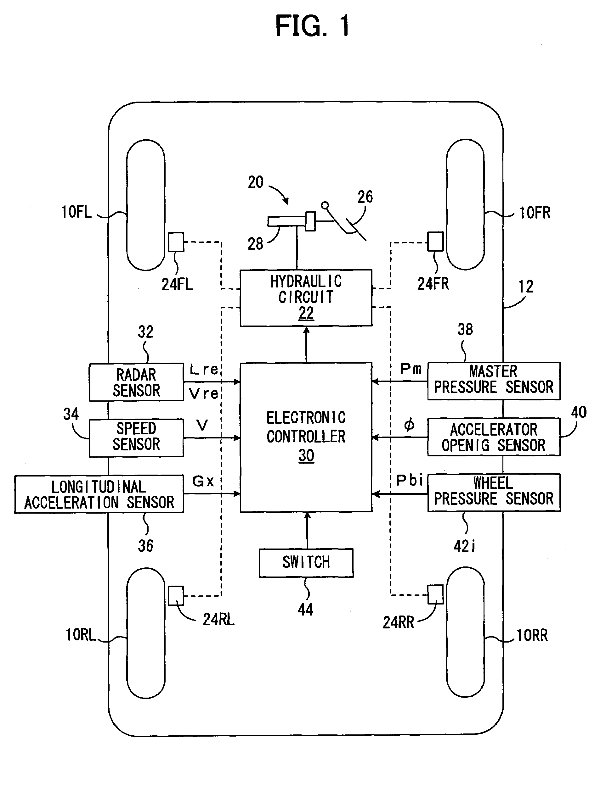
[0038]FIG. 1 diagrammatically shows a vehicle incorporating a preferred embodiment of a vehicle deceleration control device according to the present invention. In this drawing, a vehicle 12 has left and right front wheels (driven wheels) 10FL and 10FR, left and right rear-wheels (driving wheels) 10RL, 10RR. Front wheels 10FL, 10FR each are steered through tie rods with a rack-and-pinion-type power-steering device actuated in response to the rotation of a steering wheel (not shown) by a driver. A braking system 20, generating braking force on each wheel, has a hydraulic circuit 22 comprising a reservoir, an oil pump and various valves, etc. (not shown), wheel-cylinders 24FL, 24FR, 24RL and 24RR, equipped on the respective wheels, and a master cylinder 28 actuated in response to the depression of a brake pedal 26 by the driver. In the braking system, a braking pressure in each wheel cylinder, and in turn, the braking force on each wheel, are adjusted through the hydraulic circuit 22 i...


PUM


Abstract

A novel vehicle deceleration control device for ensuring a proper distance between a vehicle and a preceding vehicle, etc., equipped on a vehicle, automatically decelerates the vehicle by controlling braking force based on a target deceleration, calculated based on a relative distance and a relative speed between the vehicle and its preceding vehicle, etc., when automatic deceleration is required. The inventive device, however, will decelerate the own vehicle based on a maximum allowable deceleration when the magnitude of the target deceleration is larger than the magnitude of the maximum allowable deceleration, restricting the vehicle deceleration. The maximum allowable deceleration is determined based on the vehicle speed of the own vehicle when a predetermined condition is satisfied, and maintained at a constant or within a predetermined range, thereby enabling a driver to judge the necessity of braking operation by himself during restricting the vehicle deceleration more easily than ever.

Description

BACKGROUND OF THE INVENTION[0001]1. Field of the Invention[0002]This invention relates to a vehicle deceleration control device, and more specifically, to a vehicle deceleration control device that decelerates a vehicle through automatic braking force control.[0003]2. Description of Prior Art[0004]In the field of running control of a vehicle, such as automobile, it is known to execute deceleration control through which braking force or deceleration of a vehicle is automatically controlled based on a relative distance and a relative speed between the vehicle and its preceding vehicle or other objects in the front of the vehicle (referred to as a preceding vehicle etc. in the followings), ensuring a proper distance between the vehicle and its preceding vehicle, etc. Devices executing such deceleration control (or acceleration-and-deceleration control), for example, are shown in Japanese Patent Laid-Open Publications Nos. 2000-355232, 11-348746, 2002-67904, 10-32404, 10-297541 and 11-7...

Claims


Application Information

Patent Timeline
Patent Type & Authority Patents(United States)
IPC IPC(8): B60T7/12B60K31/00B60T7/22B60T8/00
CPCB60K31/0008B60T7/22B60T2201/02B60W2720/106
Inventor SEKI, MASATO
Owner TOYOTA JIDOSHA KK
Why Eureka
Try Eureka