Suture tensioning device

a suture and tensioning technology, applied in the field of suture tensioning devices, can solve the problems of irritation and damage, require additional revision, etc., and achieve the effect of avoiding tissue damage and irritation, and high strength

Active Publication Date: 2008-02-05
ARTHREX
View PDF15 Cites 211 Cited by
  • Summary
  • Abstract
  • Description
  • Claims
  • Application Information

AI Technical Summary

Benefits of technology

[0005]The instruments and methods of the present invention provide an apparatus and methods for cerclage fixation of fractured or weakened bone using high strength suture material. Accordingly, the suture ends can be secured with knots, thereby avoiding the potential for tissue damage and irritation presented using cerclage wires.

Problems solved by technology

Wire ends that are tucked down improperly, or that become loose, can cause irritation and damage and may require additional revision.

Method used


Image

  • Suture tensioning device
  • Suture tensioning device
  • Suture tensioning device

Examples


Embodiment Construction

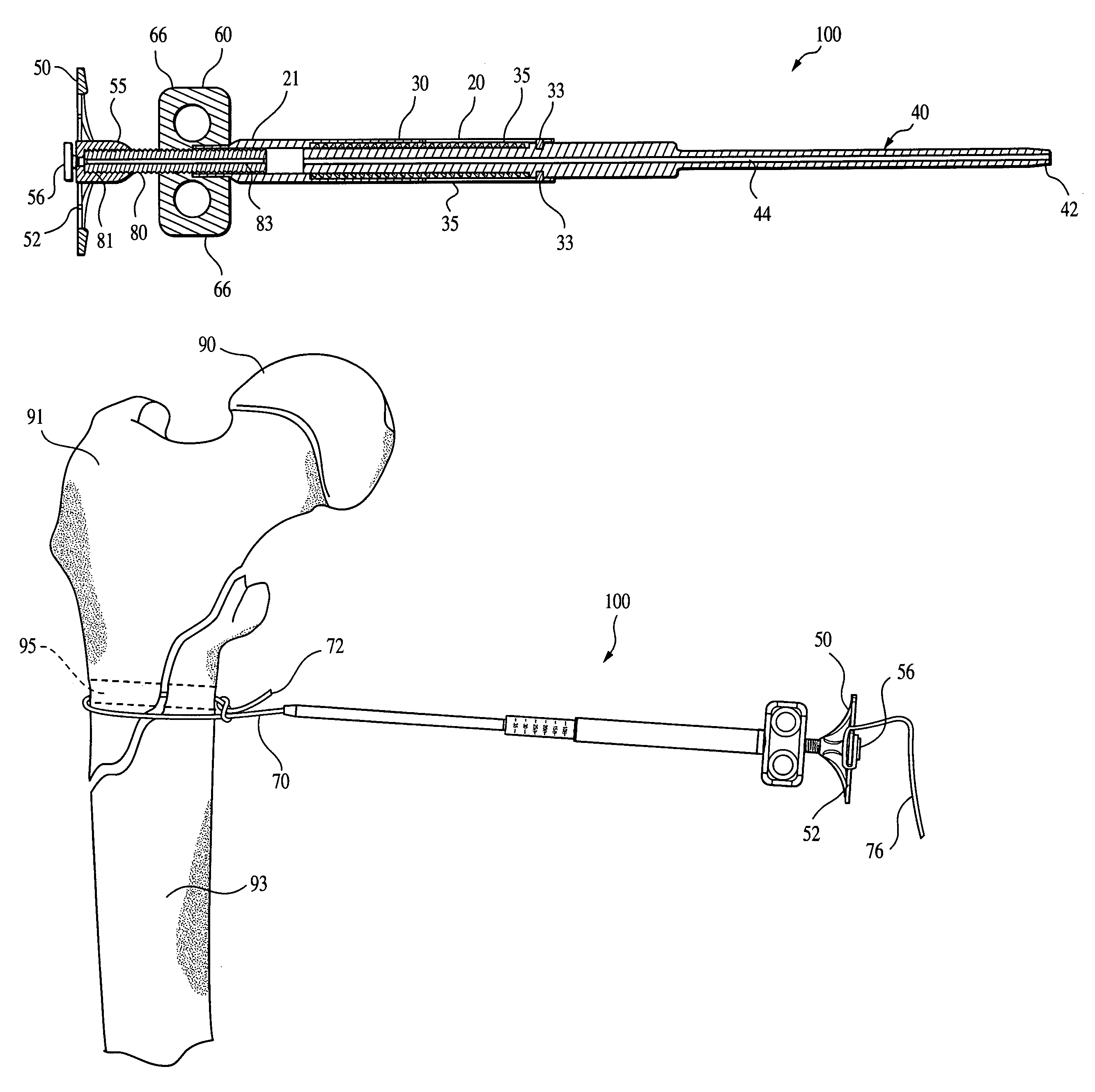
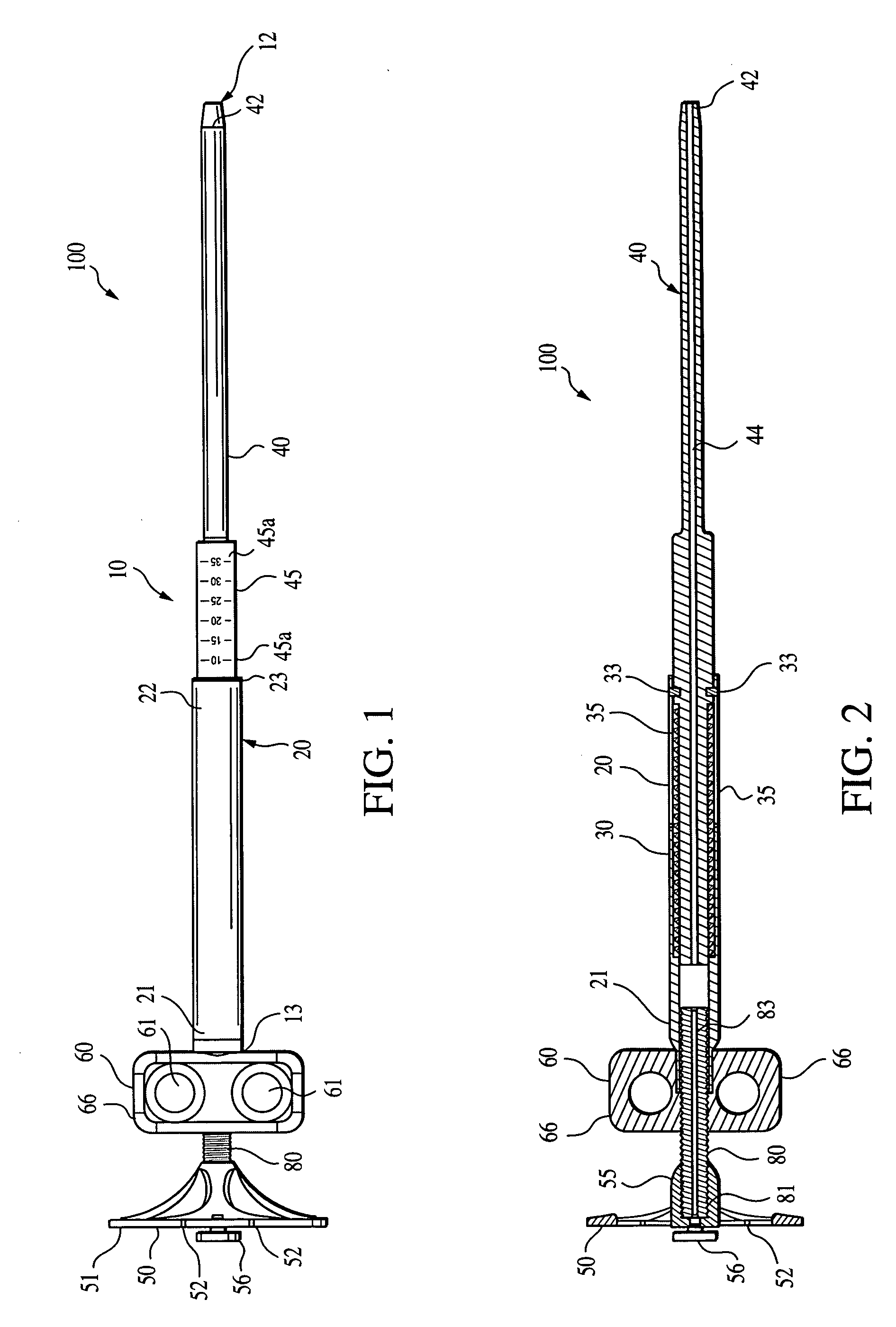
[0024]Referring now to the drawings, where like elements are designated by like reference numerals, FIGS. 1 and 2 illustrate a suture tensioning device 100 of the present invention, while FIGS. 3-7 illustrate various subcomponents of the suture tensioning device 100. Tensioning device 100 includes a cannulated elongated body 10 having a distal end 12 and a proximal end 13, as shown in FIG. 1. The body 10 of the suture tensioning device 100 includes two telescopically slidable sections: an outer shaft or outer tube section 20 and an inner shaft or inner tube section 40. The outer shaft 20 is cannulated for receiving the inner shaft 40. The outer shaft 20 is provided with a proximal end 21 and a distal end 22. A line 23 (FIG. 1) is marked at the distal end 22 of the outer shaft 20 to facilitate reading against scale numbers 45a.

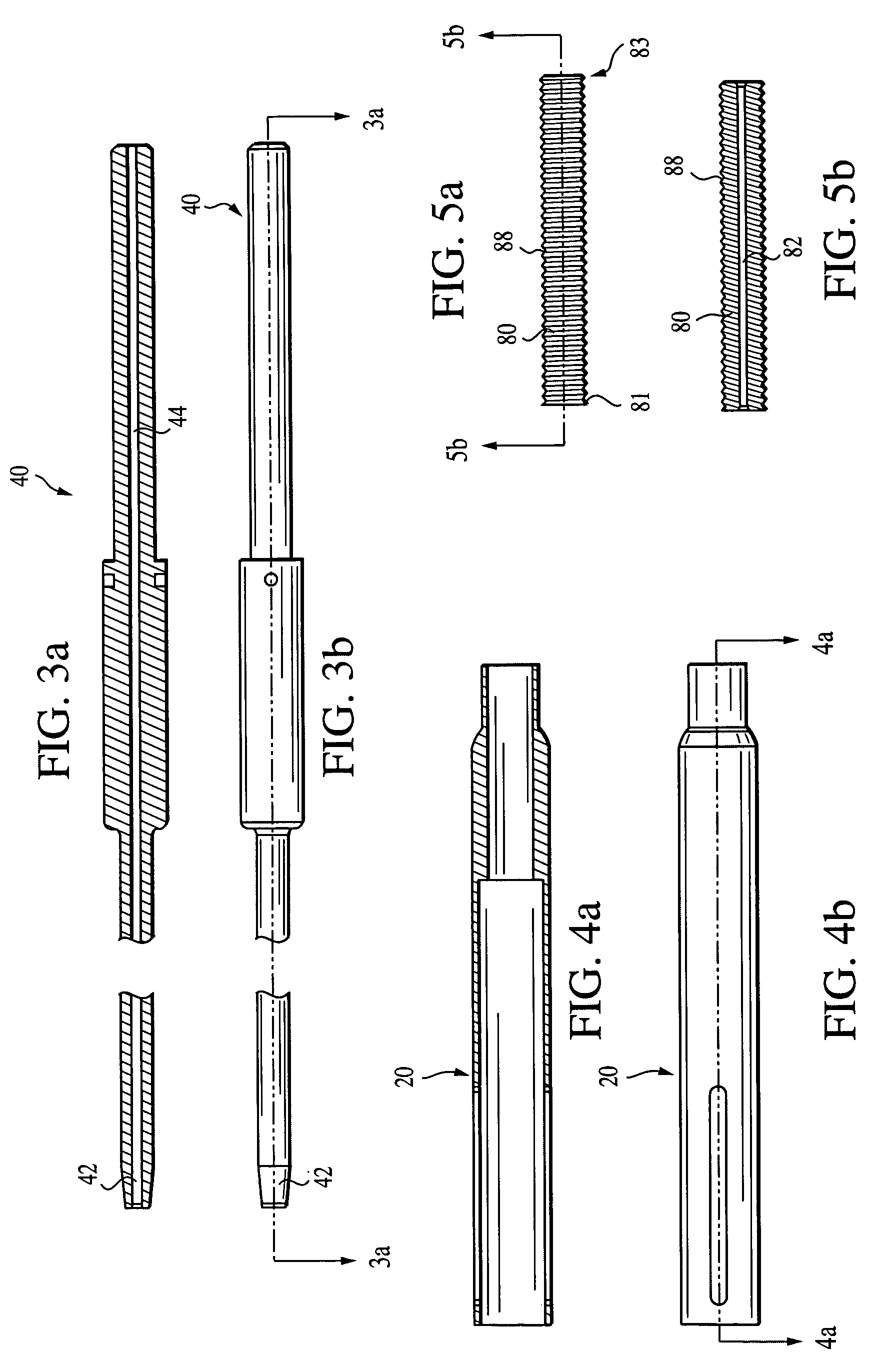
[0025]As illustrated in FIGS. 2, 3(a) and 3(b), the inner shaft 40 is also caunnulated and extends to a tapered end 42. In this manner, cannula 44 (FIGS. 2, 3...


PUM


Abstract

A device for tensioning suture which includes two telescopically slidable cannulated tubes. An adjustment wheel is coupled to and turns a threaded post which is threadingly engaged with the proximal end of one of the slidable tubes. A suture end is passed through the cannulated tubes of the suture tensioning device and secured to the adjustment wheel. Rotating the adjustment wheel counterclockwise increases the overall length of the suture tensioning device and increases tension on the suture.

Description

[0001]This application claims the benefit of U.S. Provisional Application Ser. No. 60 / 376,544, filed May 1, 2002, the entire disclosure of which is incorporated by reference herein.FIELD OF THE INVENTION[0002]The present invention relates to methods and instruments for tensioning of sutures and, more specifically, to an adjustable suture tensioning device.BACKGROUND OF THE INVENTION[0003]Bone fixation using cerclage wire is a surgical procedure for securing fractured or weakened bone. Procedures in which bone cerclage may be indicated include, for example, humeral stem fracture repair and total shoulder surgery. After the cerclage wires are tensioned and wrapped, excess wire is cut off. The wire ends are tucked down to be out of the way. Wire ends that are tucked down improperly, or that become loose, can cause irritation and damage and may require additional revision.[0004]An improved surgical technique for encircling a bone with a high strength suture material is needed. Instrumen...

Claims


Application Information

Patent Timeline
Patent Type & Authority Patents(United States)
IPC IPC(8): A61B17/04A61B17/82
CPCA61B17/0469A61B17/0483A61B17/82A61B2017/0496
Inventor DREYFUSS, PETER J.SCHMIEDING, REINHOLDROMEO, ANTHONY A.
Owner ARTHREX
Why Eureka
Try Eureka