Signal input/output device

a signal input/output device and input/output technology, which is applied in the direction of electrical apparatus casings/cabinets/drawers, substation/switching arrangement details, and support structure mounting, etc., can solve the problem of difficult to separate the strength with which adjacent signal input/output units are joined to each other by engagement of pins within holes, etc. problem, to achieve the effect of increasing strength

Active Publication Date: 2008-07-08
SMC CORP
View PDF16 Cites 30 Cited by
  • Summary
  • Abstract
  • Description
  • Claims
  • Application Information

AI Technical Summary

Benefits of technology

[0008]A major object of the present invention is to provide a signal input / output device comprising a plurality of joined signal input / output units, which can easily be separated.
[0010]According to the present invention, adjacent signal input / output units are joined to each other by means of the swingable connecting member. This arrangement allows the signal input / output units to be joined together with an increased joining strength.
[0011]No adhesive is required to join the adjacent signal input / output units. Therefore, when the number of signal input / output units is increased or reduced, e.g., when another signal input / output unit is added, or when an unwanted signal input / output unit is removed, the adjacent signal input / output units can be separated quite easily.
[0012]The connecting member of each base should preferably be secured to an engaging portion of the base by a fastening member. Once the connecting member has been positioned and fixed by the fastening member, the adjacent signal input / output units can be firmly joined together without separating, enabling the signal input / output device to be assembled with increased joining strength.
[0013]An end block, which is disposed adjacent to the signal input / output unit at one end of the array, should also preferably have a connecting member swingably supported on an end of the end block facing the signal input / output unit, whereby the connecting member engages with the stop of the signal input / output unit. In other words, the end block should preferably be joined to the signal input / output unit at the end of the array, in the same manner as the mutually adjacent signal input / output units that are joined to each other. Therefore, the signal input / output unit at the end of the array and the end block are joined to each other with an increased joining strength.
[0014]The electric signal input / output modules should preferably have insertion holes for enabling insertion of tag plates therein. For example, tag plates carrying descriptions of functions of the electric signal input / output modules are inserted into the respective insertion holes. Such tag plates and corresponding descriptions are effective to prevent a worker from incorrectly connecting cables to the electric signal input / output modules.

Problems solved by technology

However, the strength with which such adjacent signal input / output units are joined to each other by engagement of the pin within the hole is not very large.
However, once the pin is fixed in position by the adhesive, it is difficult to separate adjacent signal input / output units, for the purpose of increasing or reducing the number of signal input / output units that are used.

Method used


Image

  • Signal input/output device
  • Signal input/output device
  • Signal input/output device

Examples


Embodiment Construction

[0023]A signal input / output device according to a preferred embodiment of the present invention shall be described in detail below with reference to the accompanying drawings.

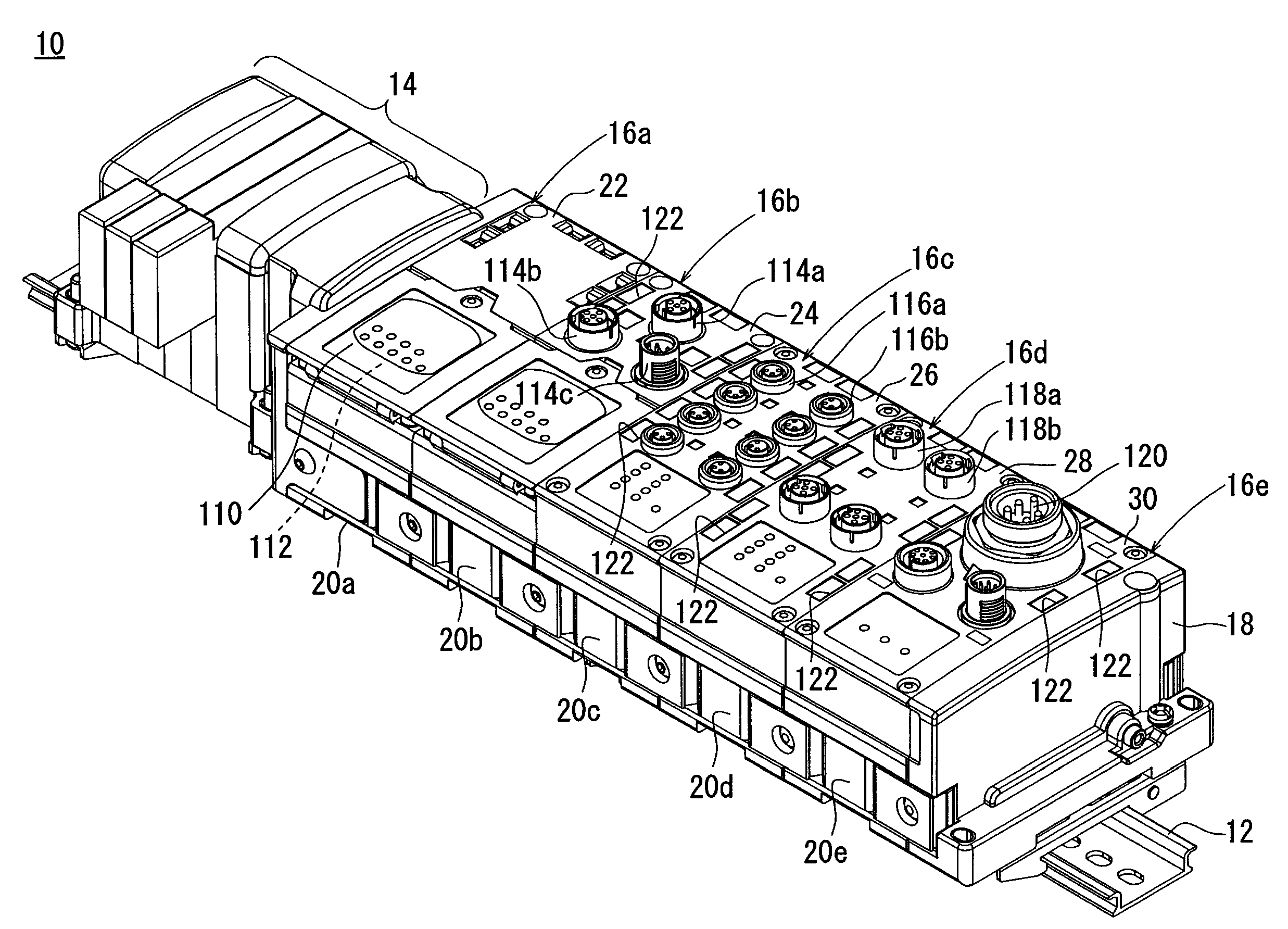
[0024]FIG. 1 shows a perspective view of a signal input / output device 10 according to the embodiment of the present invention. The signal input / output device 10 is disposed slidably on an elongate guide rail 12.

[0025]The signal input / output device 10 includes a valve manifold 14, an array of juxtaposed signal input / output units 16a through 16e with an end thereof joined to the valve manifold 14, and an end block 18 positioned at the other end of the array. The signal input / output unit 16b functions as a relay unit, for transmitting signals to a controller, e.g., a programmable controller (not shown).

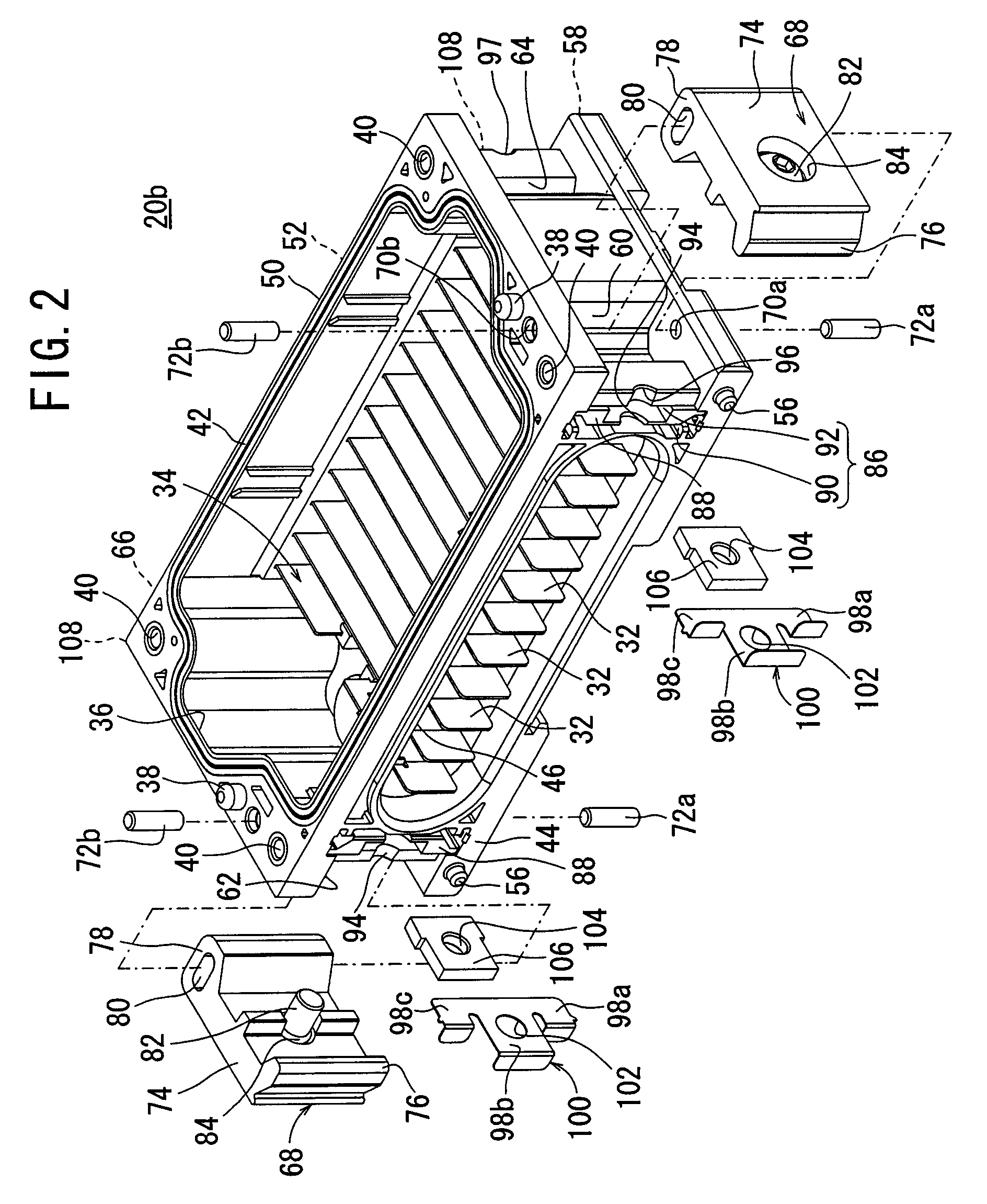
[0026]The signal input / output units 16a through 16e comprise respective signal input / output modules disposed respectively on bases 20a through 20e. Specifically, the signal input / output modules of the signal input / o...


PUM


Abstract

A signal input / output device includes an array of signal input / output units. The signal input / output units have respective bases, each of which includes a connecting member. The connecting member has a second protruding end finger swingably supported on a base, and a first protruding end finger that engages with a stop of an adjacent base. The connecting member is positioned and fixed (secured) by a screw, which extends through a bottom plate and is threaded in a square nut. The connecting member, when secured in this manner, joins the adjacent bases to each other.

Description

BACKGROUND OF THE INVENTION[0001]1. Field of the Invention[0002]The present invention relates to a signal input / output device for receiving an electric signal transmitted from a sensor, a switch, or the like, and for sending an electric signal to a solenoid-operated valve manifold or the like.[0003]2. Description of the Related Art[0004]Signal input / output devices receive control signals generated by a controller, for example, and also transmit control signals for opening or closing a valve or for energizing an external load such as a lamp, a relay, or the like, based on the received control signals. Signal input / output devices also receive signals transmitted from a sensor, a switch, or the like that is mounted on a cylinder, and transfer the signals to a controller.[0005]A signal input / output device of the above type is disclosed in Japanese Laid-Open Patent Publication No. 2002-23808. The disclosed signal input / output device includes a plurality of juxtaposed signal input / output ...

Claims


Application Information

Patent Timeline
Patent Type & Authority Patents(United States)
IPC IPC(8): H05K5/00H01R9/22H05K7/00
CPCH01R9/2608H05K7/1465
Inventor SEKINE, MITSUONOGUCHI, YUTAKASEO, MAKOTO
Owner SMC CORP
Why Eureka
Try Eureka