Field sequential lighting device and image projecting device

a lighting device and image technology, applied in the direction of fixed installation, lighting and heating equipment, instruments, etc., can solve the problem of insufficient color reproducibility of r-light, and achieve the effect of high efficiency and desirable brightness and color reproducibility

Inactive Publication Date: 2008-12-09
OLYMPUS CORP
View PDF5 Cites 22 Cited by
  • Summary
  • Abstract
  • Description
  • Claims
  • Application Information

AI Technical Summary

Benefits of technology

[0009]An object of the present invention is to provide a field sequential lighting device and an image projecting device which enable efficient use of light emitted from light sources and desirable color reproducibility.

Problems solved by technology

Therefore, as shown in FIG. 12, an intensity of the R-light (red-colored light) is weak in such conventional ultra-high pressure mercury lamps; thus, color reproducibility of the R-light is not sufficient.

Method used


Image

  • Field sequential lighting device and image projecting device
  • Field sequential lighting device and image projecting device
  • Field sequential lighting device and image projecting device

Examples


Embodiment Construction

[0047]An embodiment of the present invention is explained with reference to FIGS. 1 to 3.

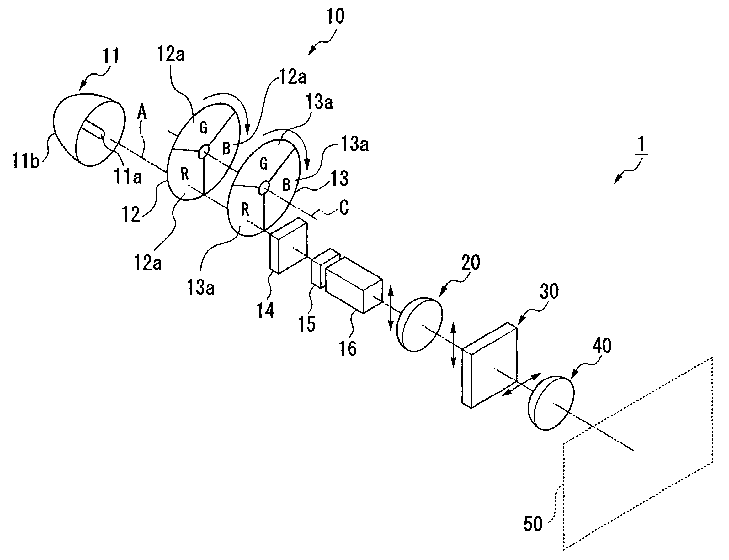
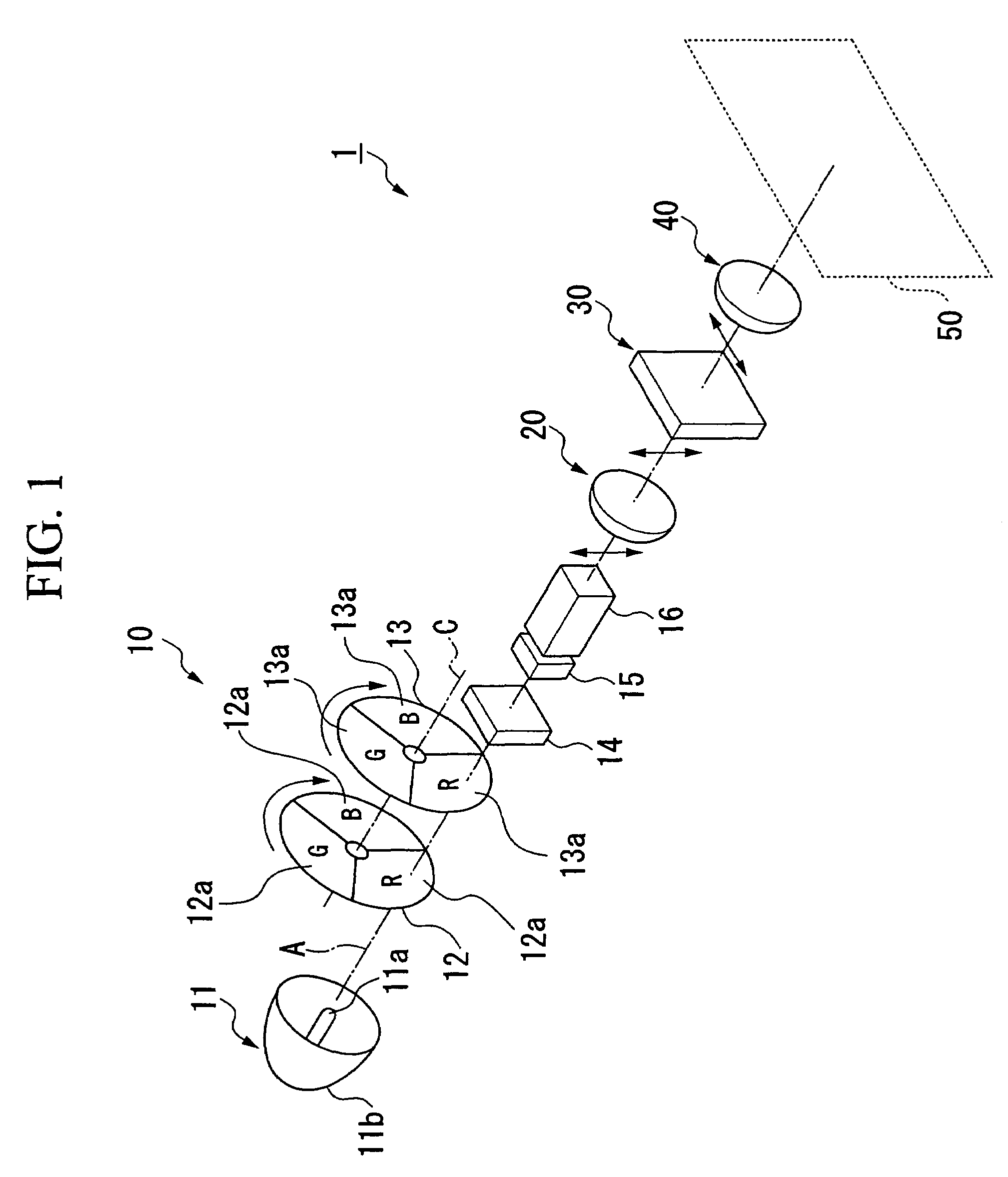
[0048]As shown in FIG. 1, an image projecting device according to the present embodiment includes: a lighting device (field sequential lighting device) 10; a lighting optical system 20 for emitting light onto a spatial modulating element 30 using the light emitted from the lighting device 10; and a projecting optical system 40 for projecting enlarged images modulated by the spatial modulating element 30 onto a screen 50. Reference symbol “A” indicates an optical axis of the image projecting device 1.

[0049]The above lighting device 10 includes: a light source 11 for emitting white light; a light converting section 12 for converting the light emitted from the light source 11 sequentially so that light corresponding to a plurality of colors (specific wavelengths) is intensified; a color wheel (color selecting section) 13, disposed between the light converting section 12 and the lighting optical sys...


PUM


Abstract

A field sequential lighting device for emitting light corresponding to a plurality of colors using a field sequential method includes: a light source; and a light converting section for intensifying the emitted light by sequentially converting the light, emitted from the light source, corresponding to the plurality of colors. By doing this, it is possible to provide a field sequential lighting device using the light emitted from the light source efficiently and having desirable color reproducibility, and an image projecting device having it.

Description

BACKGROUND OF THE INVENTION[0001]1. Field of the Invention[0002]The present invention relates to a field sequential lighting device for emitting light corresponding to a plurality of colors sequentially, and an image projecting device having the lighting device.[0003]The present application is based on a Japanese patent application filed with the Japanese Patent Office on Oct. 22, 2004 (Japanese Patent Application No. 2004-308273) and incorporates by reference its contents.[0004]2. Description of Related Art[0005]Recently, lighting devices for emitting light in a plurality of specific colors (wavelengths) have been proposed which have a light source for emitting white color light and a color wheel formed by disposing trimming (color) filters, through which light corresponding to specific wavelengths of colors, i.e., red (R), green (G), and blue (B) can be transmitted, on divided sections on a rotatable plate so that the light emitted from the light source corresponding to each color...

Claims


Application Information

Patent Timeline
Patent Type & Authority Patents(United States)
IPC IPC(8): F21V7/04F21Y101/00
CPCH04N9/3114H04N9/315H04N9/3197G03B21/204G03B33/08
Inventor YAMANAKA, KAZUYA
Owner OLYMPUS CORP
Why Eureka
Try Eureka