Ceiling mounted fan ventilation device

a ventilation device and fan technology, applied in ventilation systems, lighting and heating apparatus, heating types, etc., can solve the problem of exceeding the ambient temperature of the outside, and achieve the effect of reducing the climatic effect of the room and being easy to moun

Inactive Publication Date: 2009-03-03
SCHMIDT GARY D
View PDF26 Cites 46 Cited by
  • Summary
  • Abstract
  • Description
  • Claims
  • Application Information

AI Technical Summary

Benefits of technology

[0010]The present invention provides a solution to these as well as other needs via a ceiling mounted fan ventilation device which moves a fresh inflow of air from within a room to the attic thereof in an effective manner in order to mitigate the climatic effects on the room due to adverse ambient conditions. The fan ventilation device includes an integrally mounted thermostat to automatically turn on the fan when the ambient climate of the room needs to be moderated and turn off the fan when not needed. The device may utilize the existing hole of an attic access means such as a disappearing stairway or scuttle hole thus negating the need for extensive modifications to an existing ceiling structure. Alternatively, a method is disclosed herein whereby the fan ventilation device may be easily mounted directly to the ceiling portion of the room. Although the disclosure of the present invention is directed to a garage of a home, it is well known in the art that the present invention may be implemented in any room of any structure having an attic enclosure such as warehouses, barns, sheds, animal enclosures, prefabricated trailers, detached garages, commercial structures, outbuildings, and the like. Therefore, all of the aforementioned structures having a room to be ventilated will hereinafter be referred to as architectural structures throughout the remainder of this document.

Problems solved by technology

Because some rooms such as garages have inherently poor ventilation, the temperatures therein will exceed the outside ambient temperature.

Method used


Image

  • Ceiling mounted fan ventilation device
  • Ceiling mounted fan ventilation device
  • Ceiling mounted fan ventilation device

Examples


Embodiment Construction

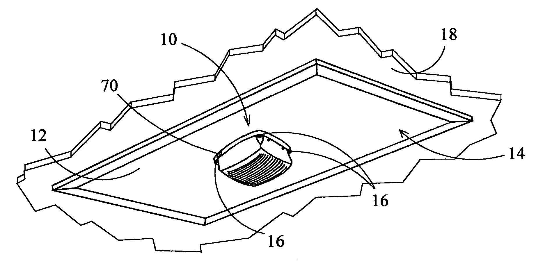
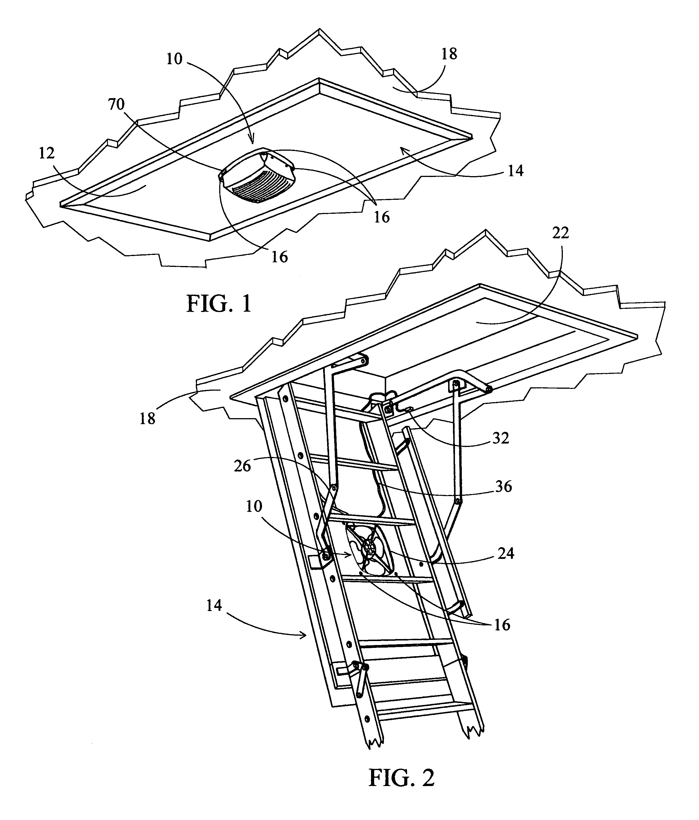
[0033]Referring now to the drawings, FIGS. 1 and 2 show a fan ventilation device 10 in operative engagement mounted beneath the flat panel 12 of a conventional disappearing stairway 14. As can be seen, the fan ventilation device 10 is unobstructive to the normal use of the disappearing stairway 14 and adds an aesthetically appealing finish to bottom surface of the stairway's panel 12. The fan ventilation device 10 is secured to the panel 12 which is typically made of one-quarter to one-half inch thick plywood using standardly available bolts 16 and associated nuts. As shown in FIG. 1, the flat panel 12 lies essentially flat with the ceiling 18 while the disappearing stairway 14 is in the contracted position and thus creates a generally airtight fit over the stairway hole 22 with the exception of a fan hole 24 which is to be described later. FIG. 2 shows the stairway 14 in the extended position in order to reveal the top portion of the fan 10 as seen through the fan hole 24. Electric...


PUM


Abstract

A ceiling mounted fan ventilation device moves a fresh inflow of air from within a room such as a garage to said attic thereof in an effective manner in order to mitigate the climatic effects on the room due to adverse ambient conditions. The device is not only capable of moderating the temperature of the room, but also augments the existing ventilation system for the attic enclosure. The device may utilize the existing hole of an attic access means such as a disappearing stairway or scuttle hole thus negating the need for extensive modifications to an existing ceiling structure. Alternatively, a method is disclosed herein whereby the fan ventilation device may be mounted directly to the ceiling portion of the room. The device may be implemented in any type of room wherein it is desirous to maintain a fresh flow of air therethrough.

Description

CROSS-REFERENCE TO RELATED APPLICATIONS[0001]Not applicable.FIELD OF THE INVENTION[0002]This invention relates to fan ventilation devices, and more particularly, to a ceiling mounted fan ventilation device which is capable of mitigating the climatic conditions within the room of an architectural structure as well as the attic enclosure thereof via a controlled inflow of fresh ambient air thereinto.BACKGROUND OF THE PRIOR ART[0003]Many homes today have a garage that is constructed as an integral part of a home's structure. This architecture creates an aesthetically pleasing design for the home as well as to provide an easy means of moving from the automobile into the home. For single story homes having a conventional garage that is adjoined to the living quarters of a home, the roof thereabove in conjunction with a ceiling creates an attic enclosure which is commonly shared thereby. Although used primarily for the storage of automobiles, the garage is also used for the storage of oth...

Claims


Application Information

Patent Timeline
Patent Type & Authority Patents(United States)
IPC IPC(8): F24F7/06F24F13/08
CPCF24F7/025
Inventor SCHMIDT, GARY D.
Owner SCHMIDT GARY D
Why Eureka
Try Eureka