
Apparatus for video graphics array testing
a video graphics array and video technology, applied in the field of apparatus for video graphics array (vga) testing, can solve the problems of time-consuming and inconvenient connection with each pin in this way
- Summary
- Abstract
- Description
- Claims
- Application Information
AI Technical Summary
Benefits of technology
Problems solved by technology
Method used
Image

Examples
Embodiment Construction
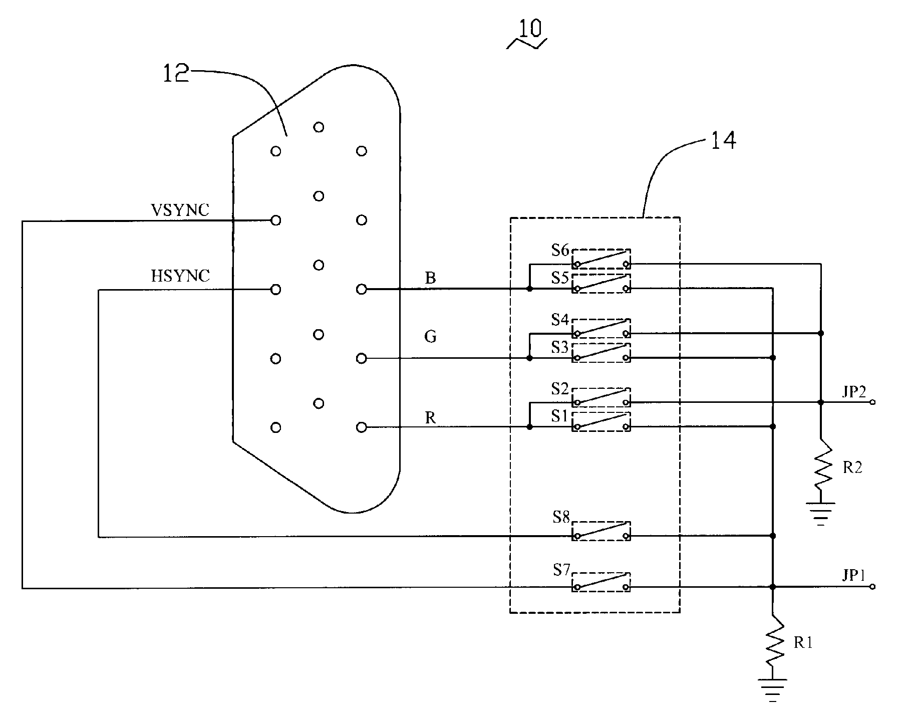
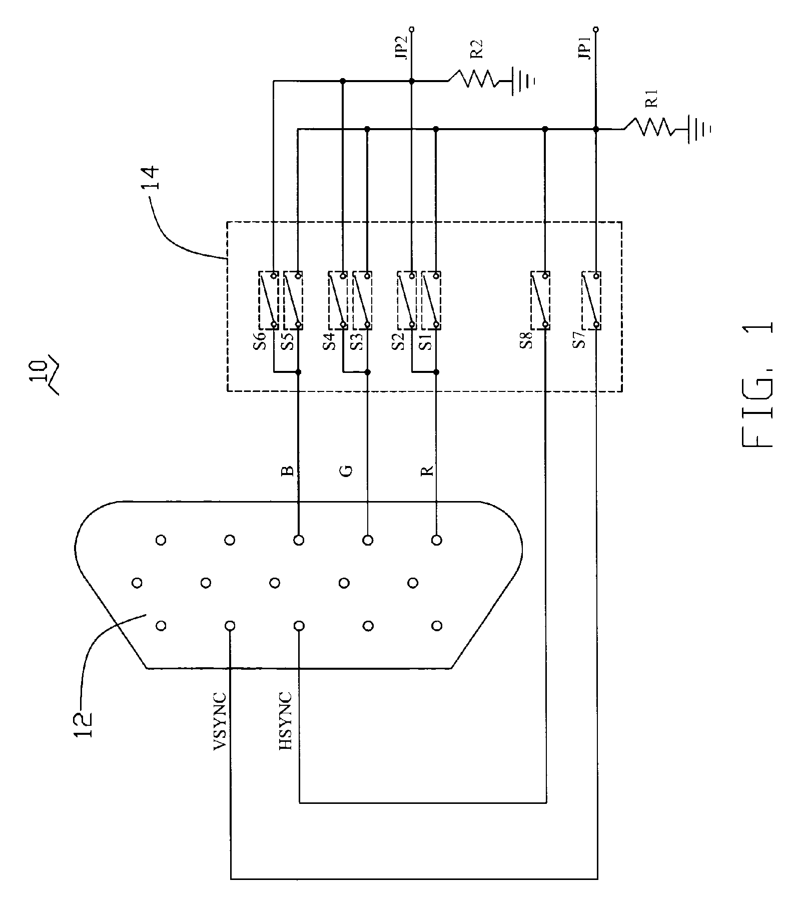
[0009]Referring to FIG. 1, an apparatus 10 includes a VGA connector 12, a switch circuit 14, a first output JP1, and a second output JP2. The VGA connector 12 includes a plurality of signal output pins such as a red signal pin R, a green signal pin G, a blue signal pin B, a vertical sync signal pin VSYNC, and a horizontal sync signal pin HSYNC. The switch circuit includes a plurality of switches S1˜S8.
[0010]The red signal pin R is coupled with the first output JP1 and the second output JP2 via the switches S1 and S2 respectively. The green signal pin G is coupled with the first output JP1 and the second output JP2 via the switches S3 and S4 respectively. The blue signal pin B is coupled with the first output JP1 and the second output JP2 via the switches S5 and S6 respectively. The vertical sync signal pin VSYNC is coupled with the first output JP1 via the switch S7. The horizontal sync signal pin HSYNC is coupled with the first output JP1 via the switch S8.
[0011]In VGA testing proc...
PUM
 Abstract
Description
Claims
Application Information