Apparatus for video graphics array testing

a video graphics array and video graphics technology, applied in the field of apparatus for video graphics array (vga) testing, can solve the problems of time-consuming and inconvenient connection with each pin in this way

Inactive Publication Date: 2007-05-17
HONG FU JIN PRECISION IND (SHENZHEN) CO LTD +1
View PDF4 Cites 3 Cited by
  • Summary
  • Abstract
  • Description
  • Claims
  • Application Information

AI Technical Summary

Problems solved by technology

It is inconvenient and time consum...

Method used


Image

  • Apparatus for video graphics array testing
  • Apparatus for video graphics array testing

Examples


Embodiment Construction

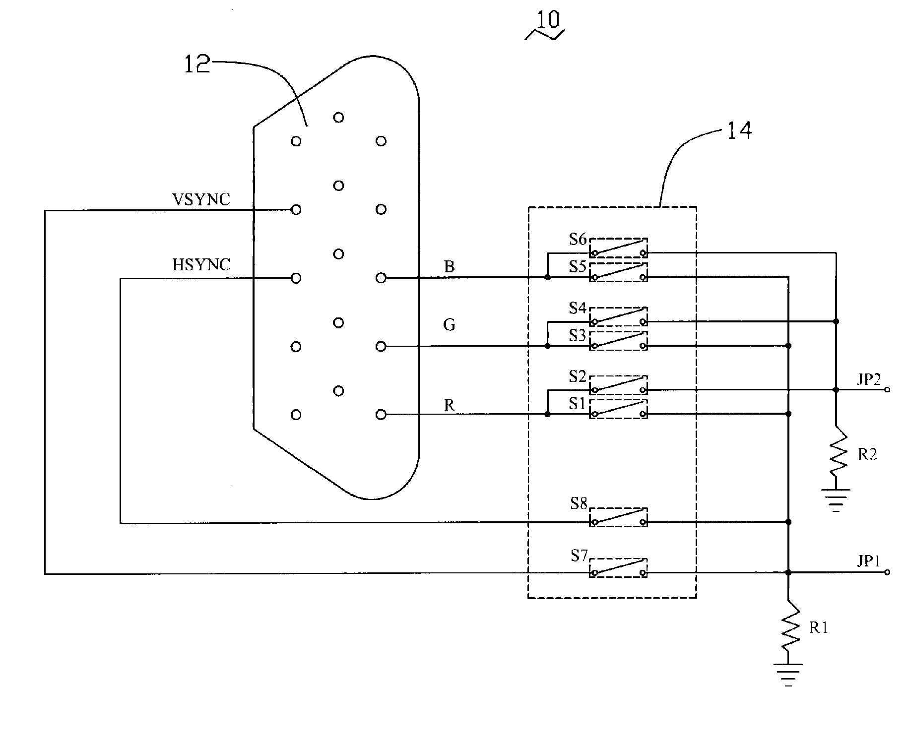
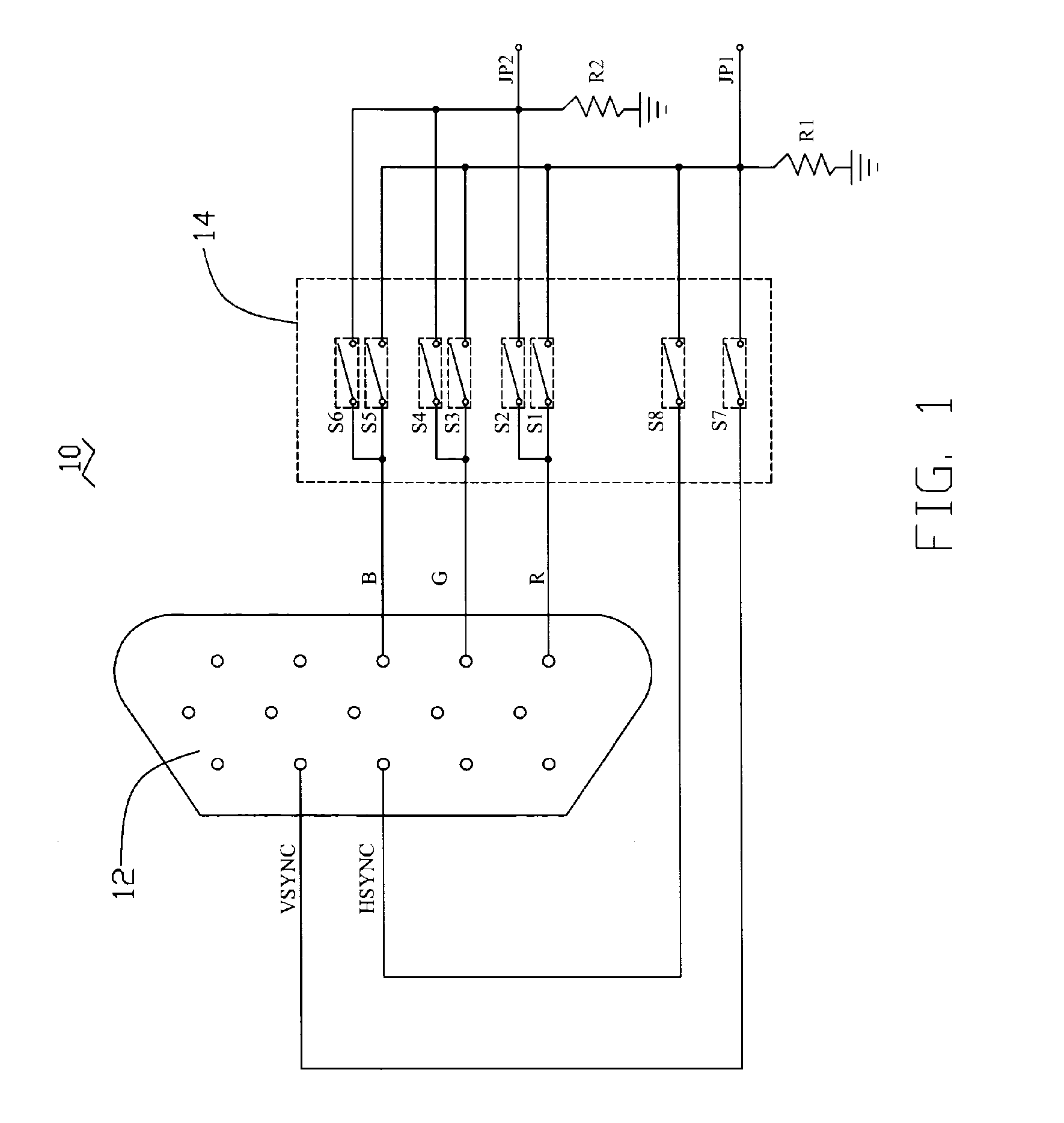
[0009] Referring to FIG. 1, an apparatus 10 includes a VGA connector 12, a switch circuit 14, a first output JP1, and a second output JP2. The VGA connector 12 includes a plurality of signal output pins such as a red signal pin R, a green signal pin G, a blue signal pin B, a vertical sync signal pin VSYNC, and a horizontal sync signal pin HSYNC. The switch circuit includes a plurality of switches S1˜S8.

[0010] The red signal pin R is coupled with the first output JP1 and the second output JP2 via the switches S1 and S2 respectively. The green signal pin G is coupled with the first output JP1 and the second output JP2 via the switches S3 and S4 respectively. The blue signal pin B is coupled with the first output JP1 and the second output JP2 via the switches S5 and S6 respectively. The vertical sync signal pin VSYNC is coupled with the first output JP1 via the switch S7. The horizontal sync signal pin HSYNC is coupled with the first output JP1 via the switch S8.

[0011] In VGA testing...


PUM


Abstract

An apparatus for video graphics array (VGA) testing includes a connector, a switch, and an output. The connector has at least one signal output pin. The signal output pin of the VGA connector is connected to the output via the switch. The output can be coupled with an oscilloscope or other similar signal analyzing device. It is simple and efficient to use the apparatus for coupling a VGA connector of a computer with an oscilloscope in the VGA testing process.

Description

FIELD OF THE INVENTION [0001] The present invention relates to an apparatus for video graphics array (VGA) testing. DESCRIPTION OF RELATED ART [0002] Generally, personal computers all use the same type of 15 pin display connector. Because that connector was used in the original IBM Video Graphics Array (VGA) card, it is often referred to simply as the VGA connector. Since the VGA connector is so widely used it acts as a standard that enables different graphic display electronics providers to provide equipment that mate with displays from different display providers. [0003] VGA connectors are widely used among all kinds of video adapters. A generic VGA connector has fifteen pins, twelve of which serve pre-determined functions. For example, the first pin is for transferring red color signals, the third pin is for transferring blue color signals, and the fourteenth pin is for transferring vertical sync signals. [0004] VGA testing is performed to test the quality of VGA signals transmit...

Claims


Application Information

Patent Timeline
IPC IPC(8): G06F13/14
CPCG09G3/006G09G5/006
Inventor DENG, XUE-FENGGUO, HAO-YULIN, HUANG-NIENWANG, TAI-CHEN
Owner HONG FU JIN PRECISION IND (SHENZHEN) CO LTD
Why Eureka
Try Eureka