Storage portion management device, image processor, method for controlling the same and computer program product

a storage portion and management device technology, applied in the field of image processors, can solve the problems of insufficient use of new functions, owner does not know the change and later know the change of data, and the user is difficult to manage the data stored in his or her box

Active Publication Date: 2011-11-15
KONICA MINOLTA BUSINESS TECH INC
View PDF19 Cites 6 Cited by
  • Summary
  • Abstract
  • Description
  • Claims
  • Application Information

AI Technical Summary

Benefits of technology

An object of the present invention is to realize management of a box that is shared by plural users in a more reliable manner than the conventional method.

Problems solved by technology

However, according to the conventional method as described in the above-mentioned documents, it is difficult for a user to manage data stored in his or her box.
Therefore, if there is a change of data in the box due to an operation of other user such as exchange of data or update of data, it can happen that the owner does not know the change and later knows the change of data.
In addition, when a new function is added, there can be users who are not aware of the addition so that the new function cannot be used sufficiently.

Method used


Image

  • Storage portion management device, image processor, method for controlling the same and computer program product
  • Storage portion management device, image processor, method for controlling the same and computer program product
  • Storage portion management device, image processor, method for controlling the same and computer program product

Examples


first embodiment

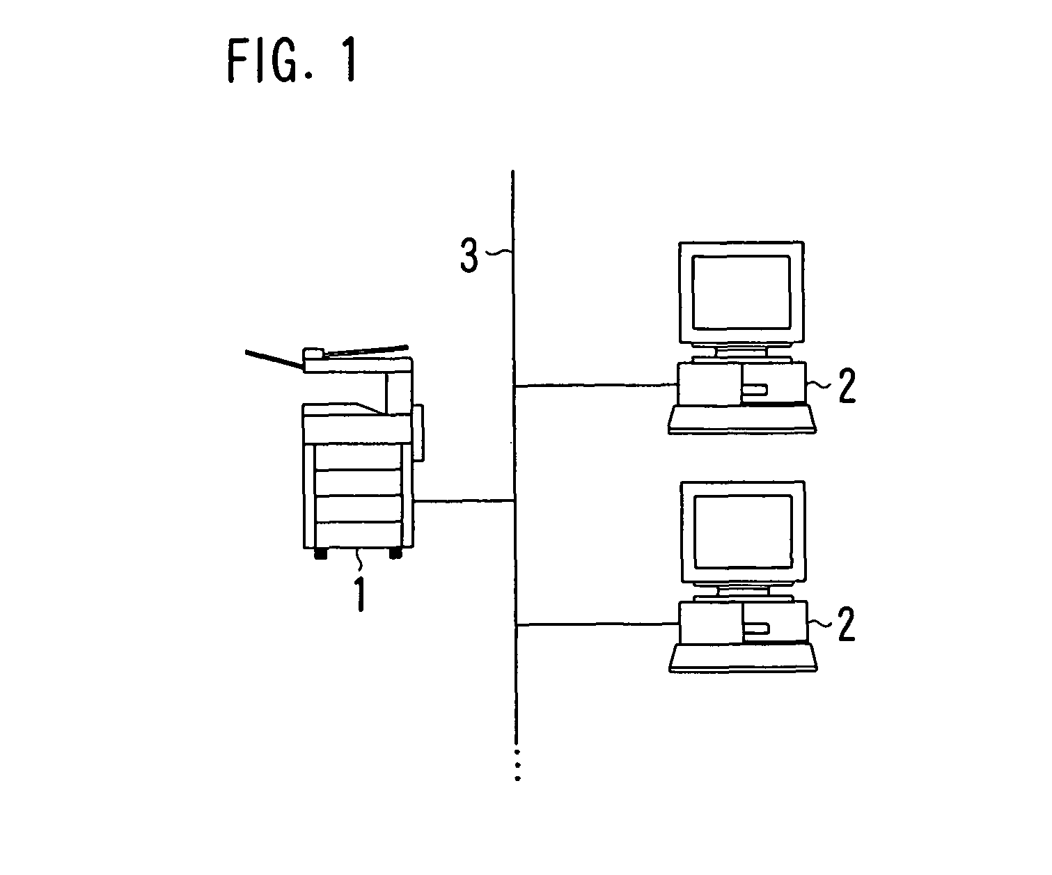
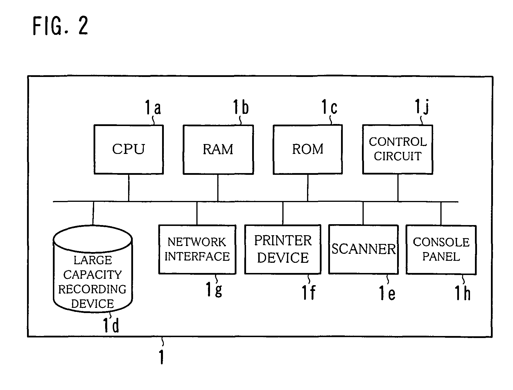
FIG. 1 shows an example of a network system that is provided with an image forming device 1 according to the present invention, FIG. 2 shows an example of a hardware structure of the image forming device 1, FIG. 3 shows an example of a console panel 1h, FIG. 4 shows an example of a functional structure of the image forming device 1 according to a first embodiment.

The image forming device 1 according to the present invention is connected to terminal devices 2 via a communication line 3 as shown in FIG. 1. As the communication line 3, a LAN, the Internet, a public telephone line or a private line can be used.

The image forming device 1 is a device having integrated functions including a copier, a network printer, a scanner, a fax and a document server. It is called a multifunction device or an MFP (Multi Function Peripherals).

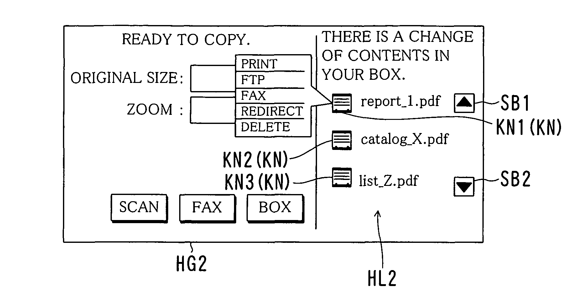
The document server provides a function in which a storage area called a “box” or a “personal box” is assigned to each user or a user group so that each user can ...

second embodiment

FIG. 16 shows an example of a functional structure of the image forming device 1 according to a second embodiment, FIG. 17 is a flowchart showing an example of a flow of a general process in the image forming device 1 according to the second embodiment, and FIG. 18 shows an example of a copy job reception screen HG3.

In the first embodiment, among files that are stored and files that were stored in the box owned by the user, files in which a change happened due to other user's operation after the user checked the contents the last time are objects of notification to the user. In the second embodiment, functions that were added to the image forming device 1 after the user used the image forming device 1 the last time are detected to be objects of notification.

A structure of the image forming device 1 in the second embodiment is basically the same as that in the first embodiment. However, as shown in FIG. 16, a new function detection portion 123 is provided instead of the inbox change ...


PUM


Abstract

An image forming device includes a box for each user for storing a file, a table management portion for storing a file change in the box together with a time when the change happened as change history information, an inbox change detection portion for detecting a file change in the box of the user when the user logs in that happened before the user logs in this time in accordance with the change history information of the box and a screen display process portion for displaying a result of the detection.

Description

This application is based on Japanese Patent Application No. 2004-307174 filed on Oct. 21, 2004, the contents of which are hereby incorporated by reference.BACKGROUND OF THE INVENTION1. Field of the InventionThe present invention relates to an image processor such as an MFP and a method for controlling the image processor.2. Description of the Prior ArtAn image forming device having functions of a copier, a network printer, a scanner and a fax is widely used. This type of the image forming device is called a multifunction device or an MFP (Multi Function Peripherals).Recently, in addition, along with improvement of a CPU performance, a large capacity of storage devices, and easy establishment of a network, a function of a document server is added to the image forming device such as the MFP, which has become commonplace and is increasingly installed in offices. This function provides each user with a storage area for each user in a hard disk drive so that each user can store data suc...

Claims


Application Information

Patent Timeline
Patent Type & Authority Patents(United States)
IPC IPC(8): G06F17/30
CPCG06F17/30067G06F16/10
Inventor MURAKAMI, MASAKAZUNAKATA, HIRONOBUSAWAYANAGI, KAZUMIKOBAYASHI, MINAKO
Owner KONICA MINOLTA BUSINESS TECH INC
Why Eureka
Try Eureka