Auto-alignable knob

a technology of rotating knobs and knobs, which is applied in the direction of mechanical control devices, domestic stoves or ranges, and container discharge methods, etc., can solve the problems of valves which couple to the knobs, valves that do not always extend in a co-lineal or correct manner towards the exterior wall of the front part of the apparatus, and valve representation, etc., to achieve sufficient diversification, good visual appearance, and good appearance

Inactive Publication Date: 2011-12-20
MABE SA DE CV
View PDF21 Cites 33 Cited by
  • Summary
  • Abstract
  • Description
  • Claims
  • Application Information

AI Technical Summary

Benefits of technology

[0019]The auto-alignable knob of the invention, allows correcting these production tolerances by means of the valve alignment with the exterior wall of the front part of the apparatus, allowing the controls to be exactly parallel between themselves in the control module.
[0021]An example knob in accordance with aspects of the present invention is made up of at least seven main parts. An offspring box is the piece coupling with the valve. A mobile box houses the offspring box. Both boxes have adequate contact surfaces between themselves. The mobile box allows the offspring box a displacement in X axis. A fixed box houses the mobile box and allows the mobile box a movement in Y axis. Furthermore, the fixed box allows the mobile box to have a certain degree of freedom so that the mobile box rotates. A knob housed in bib is coupled so that it allows a force transmission applied to rotate the knob by the user. The knob may house an insert so that the knob appearance may be diversified, however, the insert is an optional piece. The offspring box, the mobile box, the knob and the fixed box, are housed within the bib, which is capable of housing the whole knob assembly. An elastic member (biasing member), which may be a spring, allows the knob to be oppressed to operate the apparatus, allowing the knob to return to its initial position. Finally, a bib cap keeps the knob assembly assembled, the bib cap is coupled by means of hooks and cavities to the bib. The fixed box houses the elastic member assuring that said member carries out its job in keeping the appearance of the knob assembly and the position of the internal part of the knob assembly.
[0023]Therefore, it is an object of the present invention to provide a knob for home appliance apparatuses that may be correctly mounted in the valves, even with production and assembly tolerances.
[0026]It is an object of the invention providing a knob that has a good visual appearance, and thus, it is an object of the invention that the knob leaves a quality impression to the user of the apparatus.
[0027]Finally, it is an object of the present invention providing a knob that is sufficiently versatile to diversify the appearance, using the same internal system.

Problems solved by technology

The problem to solve, as was stated before, is that during assembly, the valves, which couple to the knobs, do not always extend in a co-lineal or correct manner towards the exterior wall of the front part of the apparatus.
The afore may be due to different assembly errors, for example: (a) the axis that will hold the valve or the valve, is not centered in regards to the exterior wall of the front part of the apparatus, or (b) manufacture of certain pieces, for example depending on the material which a certain piece is made, it will be subject to be bent and consequently misalign the valve in regards to the exterior wall.
However, due to an assembly error, it is possible that a valve representation (101, 102) is misaligned as shown in FIG. 1a.

Method used


Image

  • Auto-alignable knob
  • Auto-alignable knob
  • Auto-alignable knob

Examples


Embodiment Construction

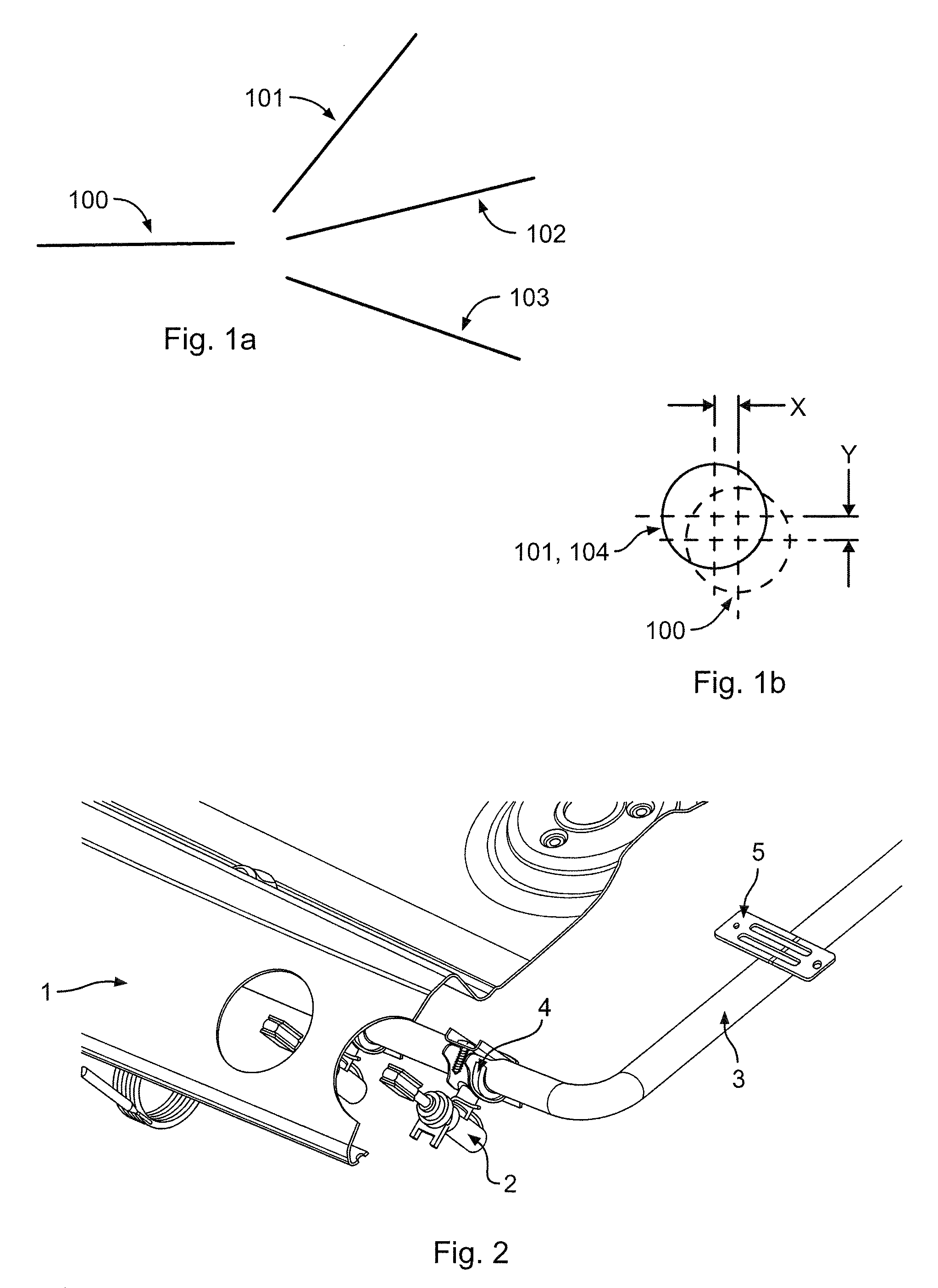
[0057]FIG. 2 shows a corner of a home appliance wall (1), wherein the wall (1) has a transversal cut showing the existing relation between the wall (1), a valve (2) and an alignment axis (3). In the figure, it is appreciated that the apparatus is an oven or range. However, it should be pointed out that the invention may be used in any type of apparatus.

[0058]An alignment axis (3) is usually used in home appliances, to hold the valves (2). The axis (3) is held by one of the home appliance walls by means of wings (5), which may be brackets. The valves (2) embrace the axis (3) by means of brackets (4), which may be fastened to the axis by diverse means, such as screws, adhesives, etcetera.

[0059]Light and easily workable materials are preferred for the axis (3). During the apparatus assembly, it is possible that the axis (3) may suffer a collision with another part. If the axis (3) suffers a collision, the axis (3) will deform. Likewise, during assembly, it is possible that the brackets...


PUM


Abstract

An auto-alignable knob for a home appliance includes an offspring box self-connectable with a valve shaft. A mobile box has at least one lateral face including a pin. The mobile box is coupled to the offspring box to allow a free movement relative to one another along a first axis. A fixed box includes an indentation and a groove. The mobile box is insertable to the fixed box by insertion of the pin of the lateral face through the groove. The pin of the mobile box provides a respective degree of freedom to the mobile box relative to the indentation of the fixed box along at least a second axis normal to the first axis. A mechanical coupling established between the indentation of the fixed box and the pin of the mobile box is configured to provide a degree of rotational freedom about one of the axes, and a combined mechanical coupling established between the offspring box, the mobile box and the fixed box is configured to provide a respective degree of freedom along a third axis perpendicular to the first and second axes.

Description

RELATED APPLICATIONS[0001]This application claims priority from Mexican application Ser. No. MX / a / 2007 / 016325 filed Dec. 18, 2007, which is incorporated herein by reference in its entirety.FIELD OF THE INVENTION[0002]The present invention refers to a rotating knob, and more specifically refers to a rotating knob for home appliances, capable of auto-aligning with communication mechanisms from said appliances, while keeping an aesthetically pleasing appearance, independent of the internal variations of the apparatus, as well as an assembly method of said knob.PRIOR ART SPECIFICATION[0003]In home appliances, particularly dishwashing machines, washing machines, dryers, stoves, ranges, ovens and general electro domestics, rotary knobs are provided so that, by means of user interaction, the operation requirements are established, programming is established, the apparatus is turned on or off, actuates the indicators, etcetera, wherein the knobs are usually coupled by brackets to actuation ...

Claims


Application Information

Patent Timeline
Patent Type & Authority Patents(United States)
IPC IPC(8): F17C13/04H01H3/10G05G1/12
CPCG05G1/12F24C3/126Y10T74/20762Y10T74/2084Y10T16/506
Inventor CASTILLO, OCTAVIO LUGO
Owner MABE SA DE CV
Why Eureka
Try Eureka