Dual locking band clamp and method of forming the same

a band clamp and double locking technology, applied in the direction of screws, threaded fasteners, hose connections, etc., can solve the problems of reducing the quality or performance of the dimple lock, the failure mode of prior art band clamps exposed to an expansive force, and the general failure of the band clamp. , to achieve the effect of reducing contact and friction, reducing energy consumption, and reducing friction during integration

Active Publication Date: 2013-04-23
BAND IT IDEX
View PDF188 Cites 32 Cited by
  • Summary
  • Abstract
  • Description
  • Claims
  • Application Information

AI Technical Summary

Benefits of technology

[0007]It is one aspect of the present invention to provide a band clamp that is comprised of a band and a buckle and that employs a dual locking feature. More specifically, embodiments of the present invention employ a lip lock and a dimple lock to secure the band around an object or objects. “Lip lock” as used herein refers to a system of bending a portion of the band around an edge of the buckle, thereby fixing the band relative to the buckle. “Dimple” or “Dimple lock” as used herein refers to a system wherein a portion of the band is deformed into an aperture formed in a different portion of the band to maintain the circumference of the band. One of skill in the art will appreciate that the deformation may also interface with the buckle to fix the band relative to the buckle. Traditionally, a lip lock or dimple lock is used exclusive of the other. Embodiments of the present invention combine these two locking methods to yield a band clamp with enhanced performance related to retained force, maximum clamping force, average loop tensile force, etc.
[0008]It is another aspect of the present invention to control retaining force, strength and long term reliability of a band clamp described herein by adjusting the depth and / or location of the dimple relative to the portion of the band that receives the dimple and relative to the buckle.
[0009]It is another aspect of the present invention to provide a band clamp that allows for visual inspection of the dimple quality. In one embodiment, a dimple lock is formed by forcing a punch through an aperture in the buckle to deform the band positioned within the buckle and to create the dimple that locks the band relative to a different portion of the band and relative to the buckle to generally fix the circumference of the band as well as prevent substantial movement of the band relative to the buckle. However, if any or all of the punch, band or buckle are mispositioned, the dimple may be misformed, which can reduce the quality or performance of the dimple lock. Thus it is contemplated that the punch used to form the dimple in the band include an outwardly extending shoulder such that when a dimple is properly made, a ring, visually flat surface or other indicator will be formed in the band adjacent to at least a portion of the perimeter of the dimple. For example, a ring formed completely around the perimeter of the dimple provides a visual indication that the dimple was formed to a proper predetermined depth and at a proper angle relative to the band.

Problems solved by technology

However, if any or all of the punch, band or buckle are mispositioned, the dimple may be misformed, which can reduce the quality or performance of the dimple lock.
More specifically, the failure mode of prior art band clamps exposed to an expansive force is typically associated with the locking feature of the buckle.
For example, band clamps generally fail when the locking lip yields which allows the band to slip relative to the buckle.

Method used


Image

  • Dual locking band clamp and method of forming the same
  • Dual locking band clamp and method of forming the same
  • Dual locking band clamp and method of forming the same

Examples


Embodiment Construction

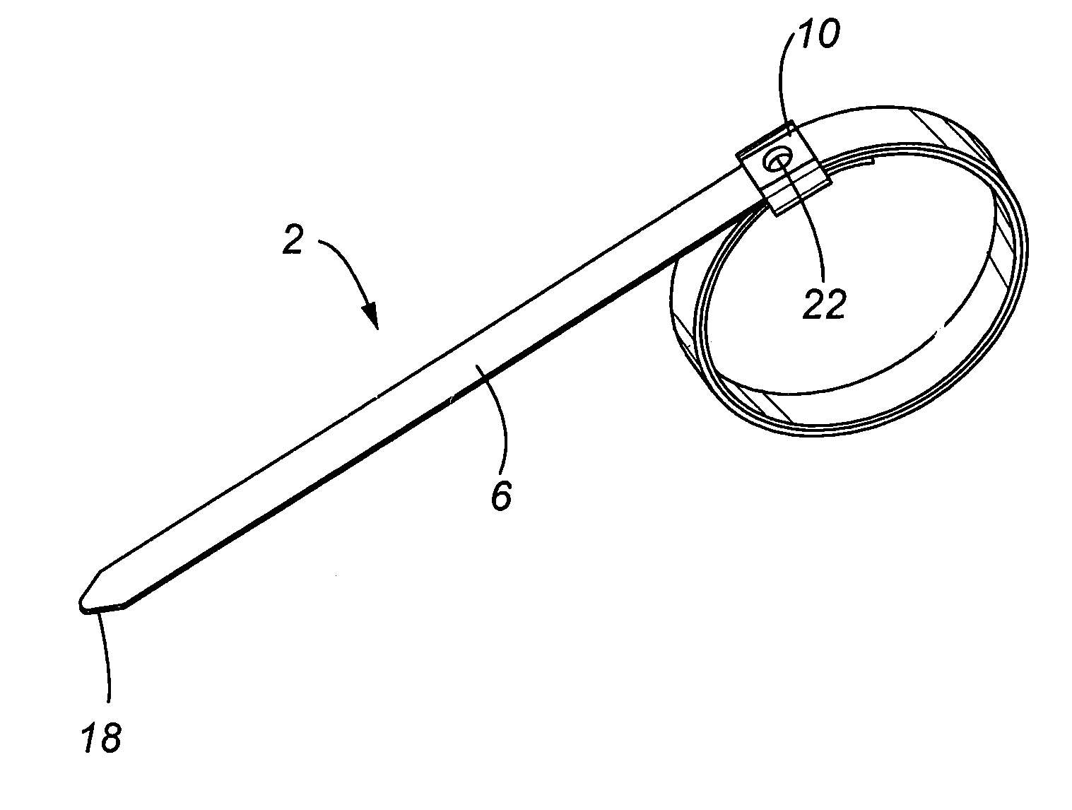
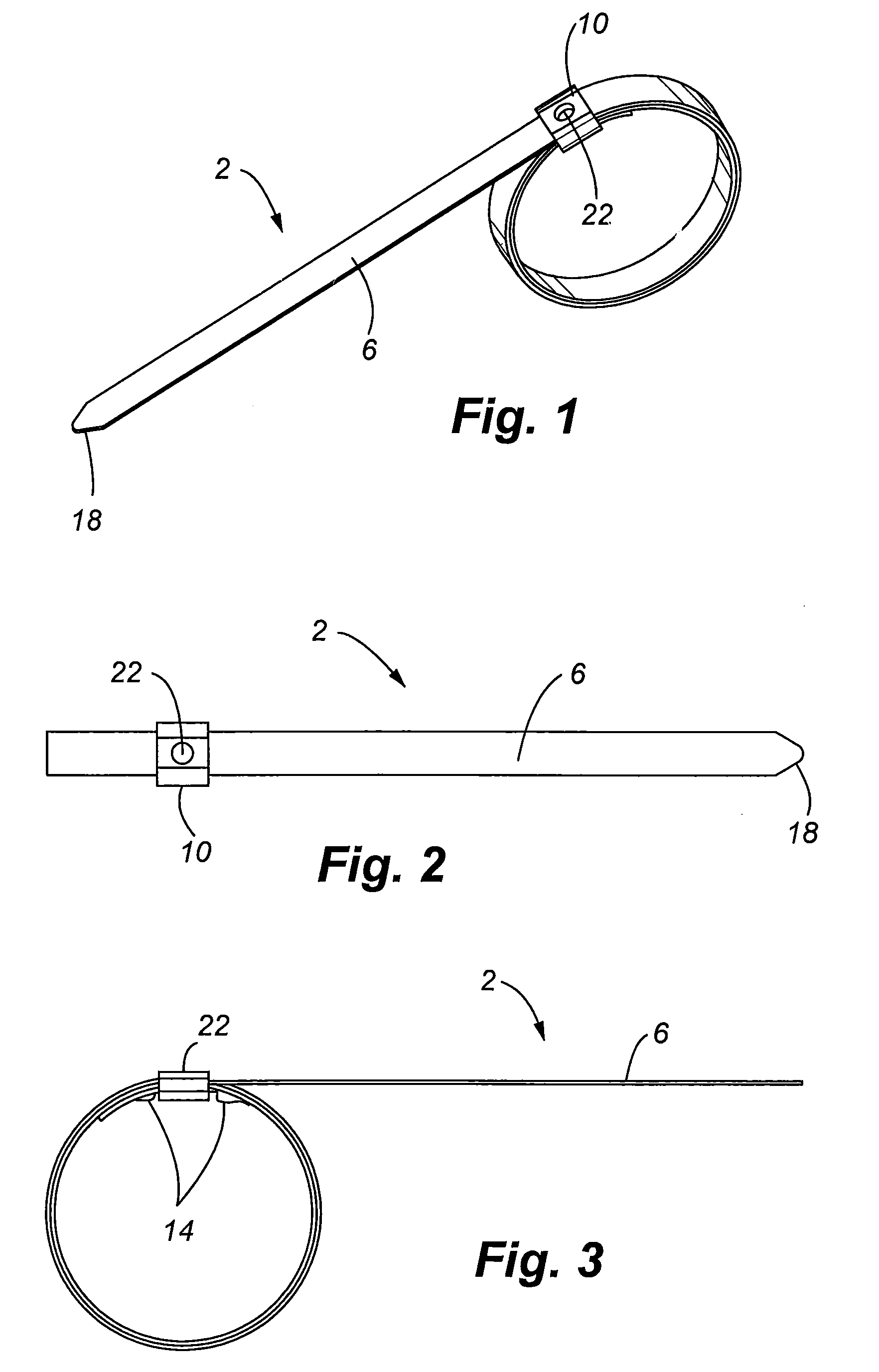
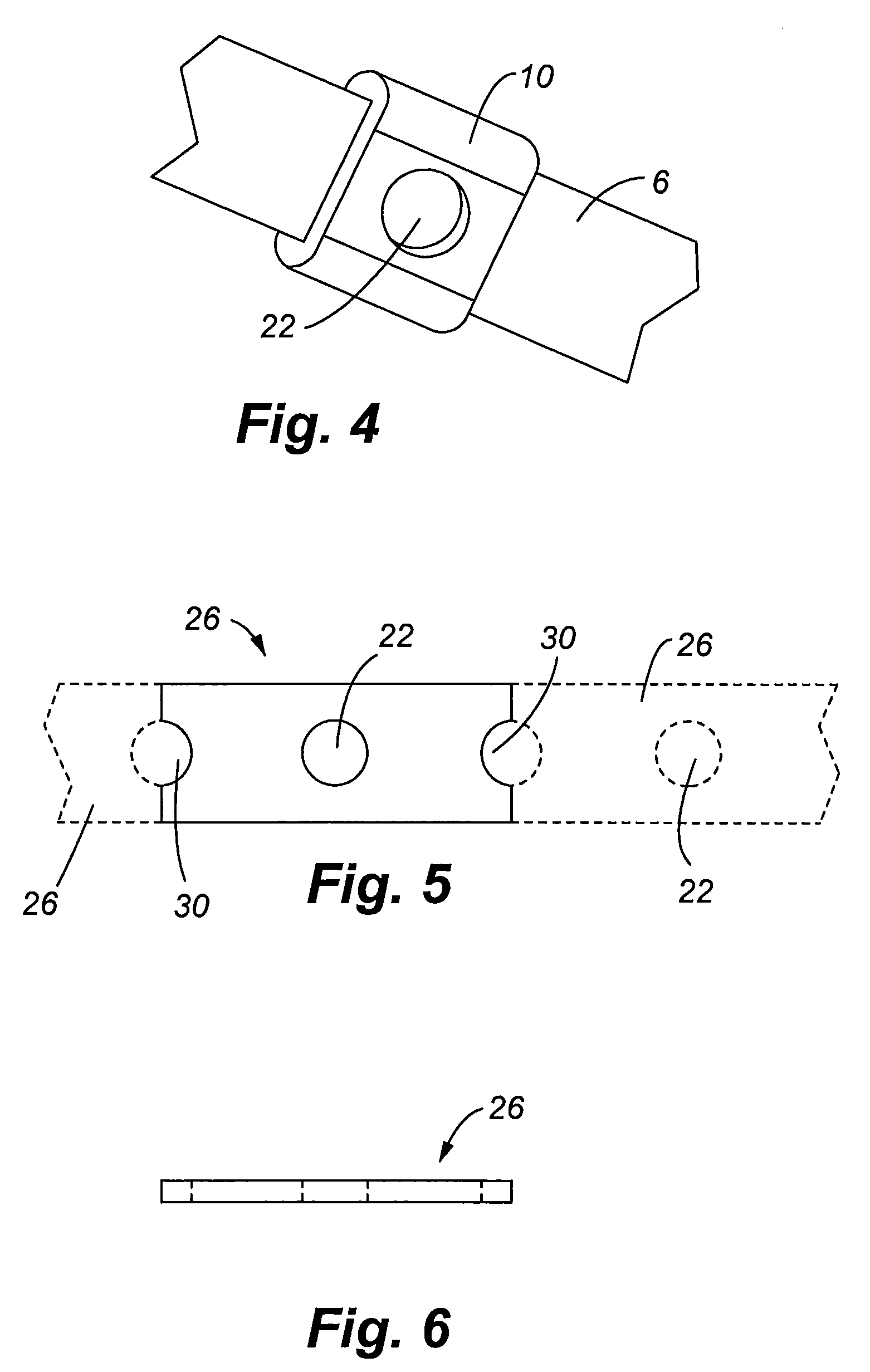
[0037]Referring now to FIGS. 1-4, one embodiment of a band clamp 2 commonly used in the art comprised of a band 6 with a buckle 10 positioned thereon is shown. The band 6 may also include at least one obstruction 14 to maintain the position of the buckle 10 on the band 6. The obstruction 14 may be in the form of dents or tabs formed in the band that engage the buckle to hold it into place. In operation, an end 18 of the band 6 is wrapped around the items being bundled and through the buckle 10. In some instances, the band 6 is wrapped multiple times about the items being bundled wherein the buckle 10 receives multiple overlapping band portions. Thereafter, a tool, i.e., punch, is used to deform the band 6 through an aperture 20 of the band 6 and, in some embodiments, through an aperture 22 of the buckle 10, thereby fixing the circumference of the band 6. The band 6 may include preformed obstructions 14 and an aperture(s), or the tool that is used to tension, deform and cut the band ...


PUM

PropertyMeasurementUnit
thickaaaaaaaaaa
thickaaaaaaaaaa
diameteraaaaaaaaaa

Abstract

An improved band clamp is provided that employs a punch that forms an indication in the deformed band during locking procedure. More specifically, a punch having at least one shoulder or other indication mechanisms is provided that selectively contacts a band to deform it with respect to a buckle to lock the band and buckle of a band clamp together. The shoulder contemplated thus leaves a mark on the deformed band to quickly provide a visual indication of dimple depth.

Description

CROSS REFERENCE TO RELATED PATENTS[0001]This application claims the benefit of pending U.S. Provisional Patent Application Ser. No. 60 / 985,142, filed Nov. 2, 2007, the entire disclosure of which is incorporated by reference herein. This application is also related to U.S. Pat. No. 5,483,998, issued Jan. 16, 1996, U.S. Pat. No. 6,014,792, issued Jan. 18, 2000, U.S. Pat. No. 5,123,456, issued Jun. 23, 1992, and U.S. Patent Publication No. 2007 / 0084022, filed Oct. 17, 2005, the entire disclosures of which are incorporated by reference in their entirety herein.FIELD OF THE INVENTION[0002]Embodiments of the present invention are generally related to band clamps that include a buckle for interconnection to a band wherein a portion of the band is threaded through the buckle and secured thereto to bundle items together or to affix one item to another.BACKGROUND OF THE INVENTION[0003]Band clamps are widely used in a variety of applications. Band clamps generally include a band which is forme...

Claims


Application Information

Patent Timeline
Patent Type & Authority Patents(United States)
IPC IPC(8): F16L33/00
CPCB21D22/04B65D63/08B65B13/02Y10T24/14Y10T24/49Y10T24/1465Y10T24/1457B65B13/027
Inventor DORNEMAN, CASEY JAMESMARELIN, MIKLOS BALAZS
Owner BAND IT IDEX
Why Eureka
Try Eureka