Image forming apparatus

a technology of image forming apparatus and forming tube, which is applied in the direction of electrographic process apparatus, instruments, optics, etc., can solve the problems of insufficiently meeting inability to maintain the optimum density tone characteristics, and inability to meet the recent demand for increased stability. , to achieve the effect of maintaining toner charge characteristics and reducing unnecessary downtime and wasteful toner consumption

Inactive Publication Date: 2014-01-28
CANON KK
View PDF7 Cites 6 Cited by
  • Summary
  • Abstract
  • Description
  • Claims
  • Application Information

AI Technical Summary

Benefits of technology

[0011]The present invention enables realization of an image forming apparatus that maintains toner charge characteristics after auto tone correction processing and reduces unnecessary downtime and wasteful toner consumption when performing auto tone correction processing.

Problems solved by technology

However, a problem with auto tone correction processing is that if there is a change in the state, such as the toner charge characteristics, of the developing material after auto tone correction processing, in some cases, optimum density tone characteristics can no longer be maintained.
However, with this method, since the density of the patch image on the image carrier is the density before transfer and fixing steps, the accuracy may be inferior to that of auto tone correction processing, which uses the density of the image formed on the recording material, and therefore this method cannot sufficiently meet the recent demand for increased stability.
Furthermore, since it is necessary to form a multi-tone patch image in order to enhance the effect of this method, downtime during image formation increases and the amount of toner used also increases, and therefore desired cost effectiveness cannot be achieved.
However, in this state, a malfunction may occur because the developing material is not in a desired state, that is, for example, the toner charge amount is low.
Specifically, it is expected that deterioration in image quality (a decrease in graininess (roughness), background fog, white spots due to transfer defects, and the like), scattering of toner, and the like will occur.

Method used


Image

  • Image forming apparatus
  • Image forming apparatus
  • Image forming apparatus

Examples


first embodiment

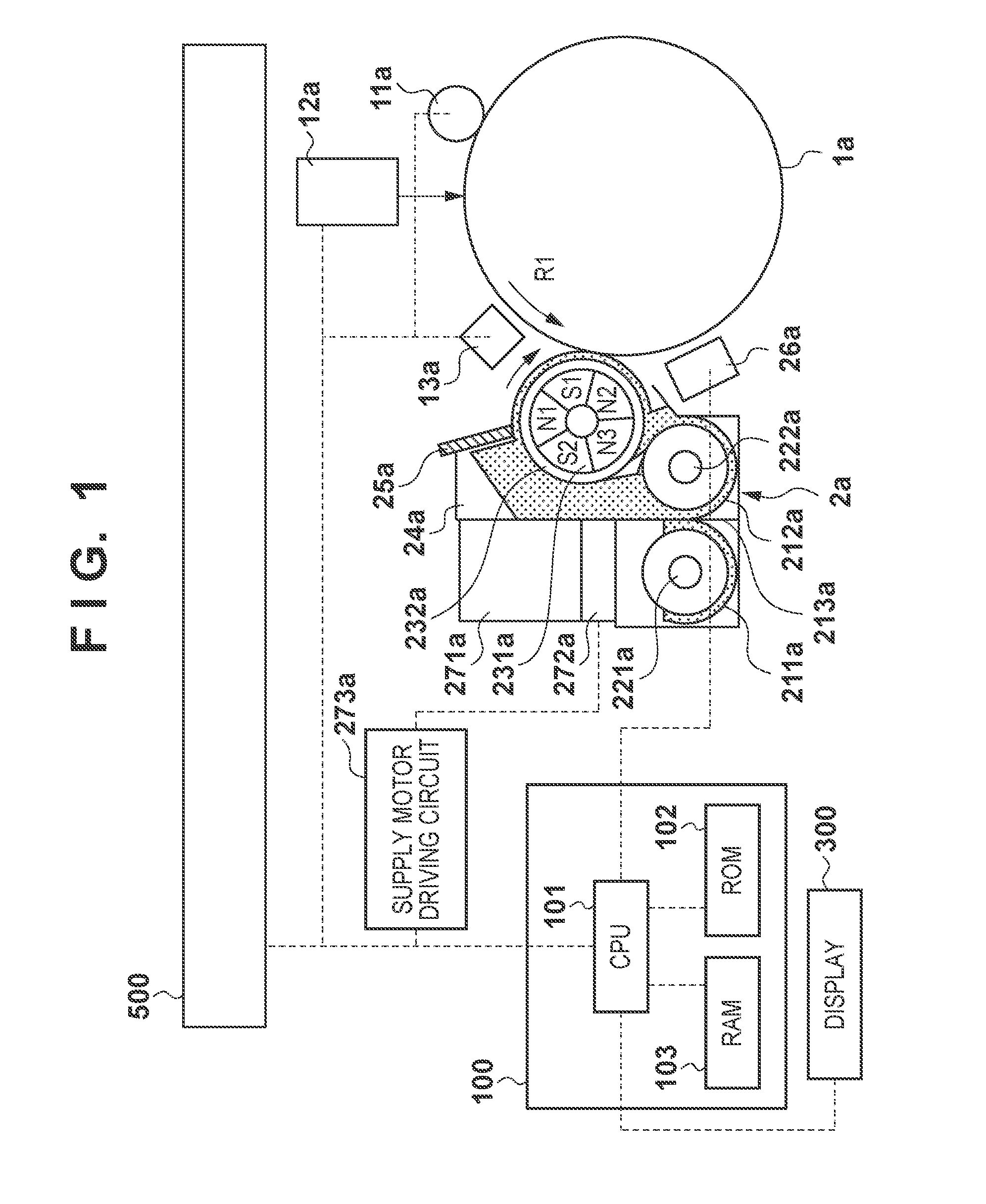
[0091]Hereinafter, a first embodiment of the present invention will be described with reference to FIGS. 18 to 21. As described above, if the state, such as the toner charge characteristics, of the developing material changes after the auto tone correction processing, in some cases, optimum density tone characteristics can no longer be maintained. FIG. 18 shows specific results of verification. In FIG. 18, the horizontal axis represents the number of output sheets (A4 size), and the vertical axes represent the result of detection by the patch detection ATR sensor 26 of an image forming apparatus according to the present embodiment, the toner charge characteristics Q / M of a developing material image on the photosensitive drum 1, the result of measurement of the reflection density of a monochromatic toner image of an image signal having a signal level of 255 (the measurement was conducted using a reflection densitometer manufactured by X-Rite, Incorporated), and changes in the set val...

second embodiment

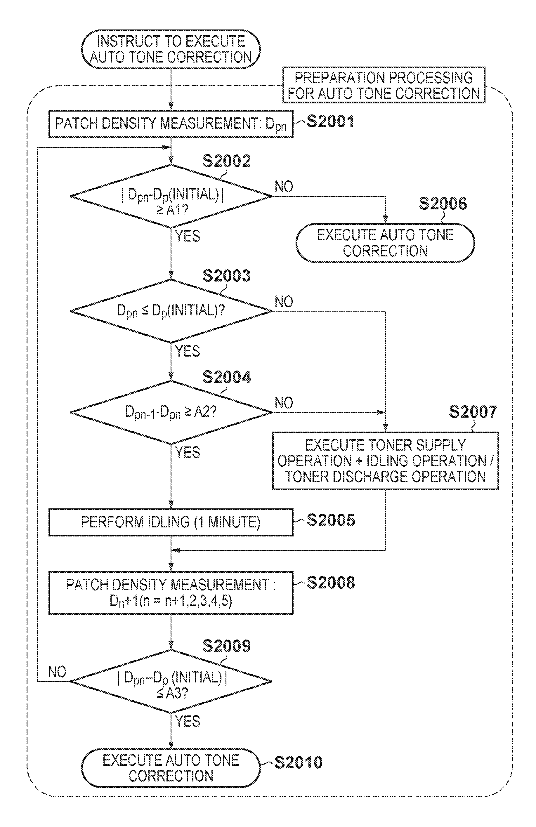
[0107]In the above-described first embodiment, the patch density was measured, and the “preparation processing for auto tone correction processing” was performed based on the measured value. However, with this method, it is necessary to always form a patch image. Even though it is necessary to perform this step in such a situation where the patch density significantly deviates from the initial value (for example, after being left to stand for a long period of time, or due to environmental fluctuation), in the case where auto tone correction processing is performed in order to adjust the tint even more during use of the image forming apparatus, it is not necessary to execute the above-described preparation processing for auto tone correction processing. In other words, during use of the image forming apparatus, the charge characteristics of the developing material are kept within the predetermined range by the patch detection ATR control, and therefore there is no point in forming a ...


PUM


Abstract

The present image forming apparatus forms a reference developing material image on an image carrier using an exposure unit and a developing unit before executing auto tone correction processing, and detects the density of the reference developing material image formed on the image carrier. If the detection result indicates that the toner charge amount of the developing material contained in the developing unit is within a predetermined range, auto tone correction processing is executed, whereas if the detection result of the density detecting unit indicates that the toner charge amount of the developing material contained in the developing unit is outside the predetermined range, adjustment processing for adjusting the toner charge amount of the developing material contained in the developing unit to be within the predetermined range is executed before execution of auto tone correction processing.

Description

BACKGROUND OF THE INVENTION[0001]1. Field of the Invention[0002]The present invention relates to an image forming apparatus, such as a copier or a printer, that uses an electrophotographic method or an electrostatic recording method.[0003]2. Description of the Related Art[0004]Among image forming apparatuses, so-called laser printers that use an electrophotographic method, in which a photosensitive member is charged and an image is exposed using a laser beam and developed, are known. Such laser printers have advantages of high image quality, high speed, and the like and are in widespread use as, for example, output apparatuses such as copiers or ordinary printers. A developing device provided in such an image forming apparatus uses a one-component developing material mainly composed of a magnetic toner or a two-component developing material mainly composed of a non-magnetic toner and a magnetic carrier. In particular, most developing devices of image forming apparatuses for forming ...

Claims


Application Information

Patent Timeline
Patent Type & Authority Patents(United States)
IPC IPC(8): G03G15/10G03G15/01
CPCG03G15/0824G03G15/5041G03G15/0849
Inventor OKADA, NORIYUKI
Owner CANON KK
Why Eureka
Try Eureka