Image forming apparatus and image forming method

Inactive Publication Date: 2008-09-25
RICOH KK
View PDF2 Cites 3 Cited by
  • Summary
  • Abstract
  • Description
  • Claims
  • Application Information

AI Technical Summary

Benefits of technology

[0016]According to the embodiments of the present invention, it is not necessary to draw a color shift detection pattern, thereby making it possible to shorten correction time and reduce wasteful toner consumption. More

Problems solved by technology

Meanwhile, the color shift in the sub-scanning direction on a photosensitive body is susceptible also to variations in the mounting positions of the optical device and a photosensitive body unit.
Therefore, the methods of Patent Documents 1 and 2 cannot correct the color shift in the sub-scanning direction due to facto

Method used


Image

  • Image forming apparatus and image forming method
  • Image forming apparatus and image forming method
  • Image forming apparatus and image forming method

Examples


first embodiment

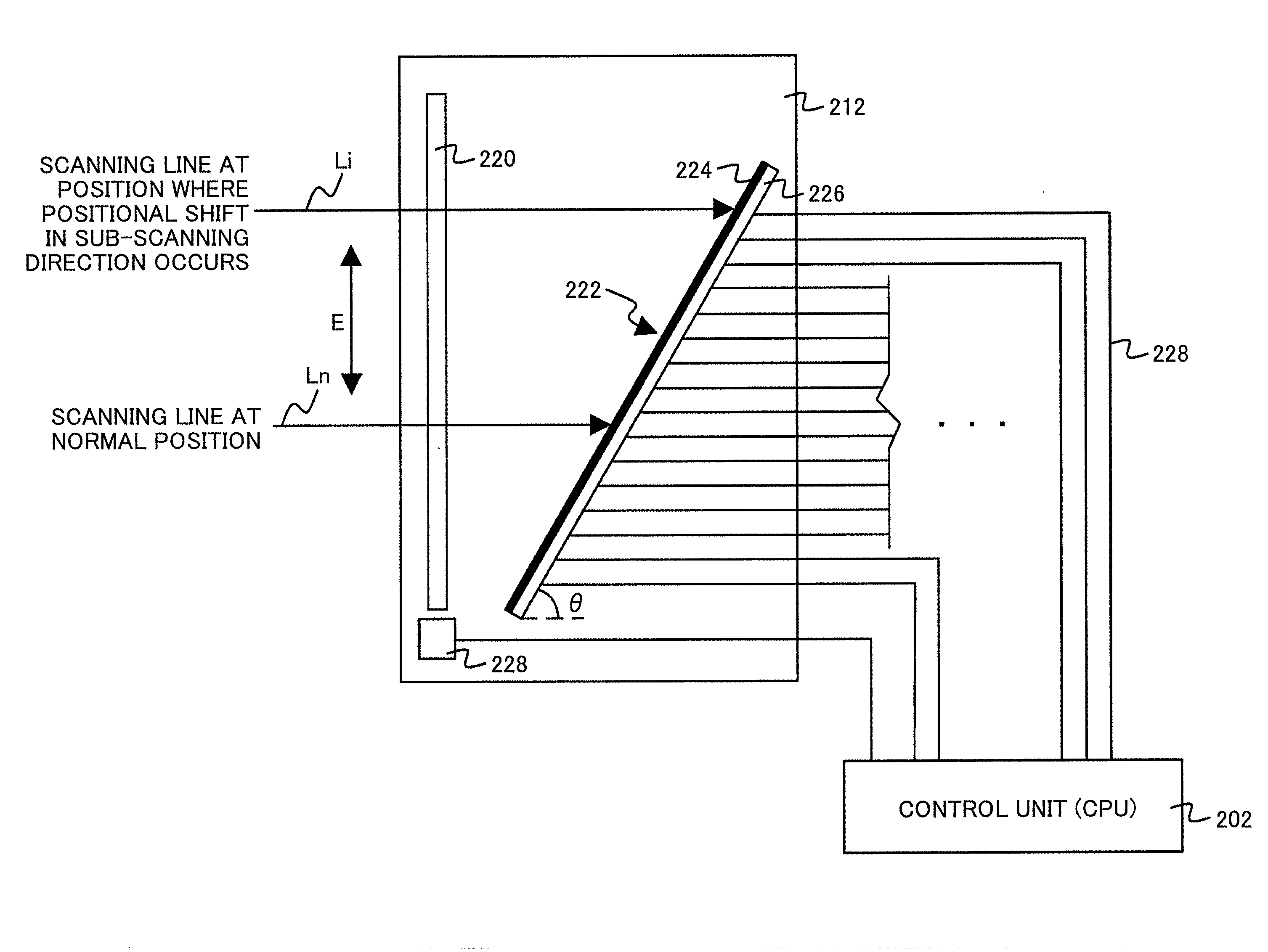
[0056]In the case of the first embodiment shown in FIG. 4, an amount for correcting the positional shift in the sub-scanning direction can be calculated by the following formula (1) using the values of T1 and T2 based on the irradiation signal 400.

[Formula 1]

[0057]

y=CONST×(T2−T1)×tan θ  (1)

[0058]wherein CONST represents the moving speed (mm / s) of an optical beam in the main scanning direction and is determined by the rotational speed of the polygon mirror 102c. Furthermore, y represents a scanning shift amount (mm) in the direction orthogonal to an optical beam in the sub-scanning direction, T1 and T2 represents a time difference until the detection signal is acquired, and θ represents an angle (rad or deg) of the irradiation position sensor relative to an optical beam.

[0059]According to another embodiment of the detection device 212, it is also possible to directly detect a difference between the scanning positions of the optical beams Ln and Li to measure a shift amount in the sub...

second embodiment

[0061]FIG. 6 shows a detection circuit including the CPU 202 and a control method. The CPU 202 is configured to be an ASIC including a system clock input port 604 and a reset port 606. Furthermore, the CPU 202 is composed of an output port 602 including plural ports and an input port 608 including plural ports that receives the detection signals from respective channels of the light receiving element. A gate signal 610 is generated as a pulse having a predetermined gate width, and in the embodiment shown in FIG. 6, a pulse train of delay time in which plural gate signals are sequentially set is generated over a gate period TG. The gate signal is used as the gate signal of the optical sensor 226. Where the emission of light attributable to an optical beam is detected when a gate potential is asserted (HIGH in the embodiment shown in FIG. 6), the detection signal is generated so that the gate potential is asserted LOW. Note that the time interval of the gate signal and the gate period...

third embodiment

[0063]FIG. 7 shows the detection circuit including the CPU 202 and the control method. In the embodiment shown in FIG. 7, the CPU 202 generates the gate signal 610 from the output port 602 over the gate period TG. On the other hand, the optical sensor 226 is made of a two-dimensional photodiode array, a CCD, or a CMOS sensor comprising a two-dimensional channel. In the optical sensor 226, a row address and a column address are specified for each channel, and the optical sensor 226 sends the output of the addresses to the CPU 202 via an appropriate interface. The CPU 202 acquires the values of the row address and the column address of the channel where the detection signal is asserted. Then, in order to control the position in the sub-scanning direction, the CPU 202 calculates the shift amount of the optical beam Li in the sub-scanning direction by referring to the shift amount data of the look-up table or the like in which are stored the differences between the values of the acquire...


PUM


Abstract

An image forming apparatus is disclosed that has an optical device including an optical source that is driven corresponding to image data, a deflection unit that deflects an optical beam output from the optical source in a main scanning direction, and an optical element that reflects the optical beam onto a photosensitive drum; a detection device that is arranged outside the optical device and detects a positional shift of the optical beam in a sub-scanning direction defined as a direction orthogonal to the main scanning direction; and a control unit that corrects the positional shift in the sub-scanning direction using an output from the detection device.

Description

BACKGROUND OF THE INVENTION[0001]1. Field of the Invention[0002]The present invention relates generally to image forming apparatuses and, in particular, to an image forming apparatus and an image forming method that correct out of sync conditions in a sub-scanning direction.[0003]2. Description of the Related Art[0004]Image forming apparatuses using an optical device are configured to scan a photosensitive body in such a way that an optical beam generated by a semiconductor laser, a laser diode, etc., is modulated with image data and deflected in a main scanning direction with a deflection unit (hereinafter referred to as a polygon mirror) to pass through an fθ lens.[0005]In typical color image forming apparatuses, the shape and the refractive index of a plastic lens are changed due to variations in the optical device and the characteristics of the plastic lens as well as changes in an environmental temperature and an in-machine temperature. As a result, the image forming position a...

Claims


Application Information

Patent Timeline
IPC IPC(8): G03G15/00
CPCG03G15/0435G03G15/326
Inventor SHUKUYA, YUICHIRO
Owner RICOH KK
Why Eureka
Try Eureka