Self-calibratable oscillating device and method and ASIC thereof

a self-calibrating, oscillating technology, applied in the direction of oscillating generators, measurement devices, instruments, etc., can solve the problems of a dramatic increase in the total testing cost of the oscillating device b>10/b>, and achieve the effect of shortening the calibration time and lowering the total testing cos

Active Publication Date: 2006-04-18
ELITE SEMICON MEMORY TECH INC
View PDF7 Cites 29 Cited by
  • Summary
  • Abstract
  • Description
  • Claims
  • Application Information

AI Technical Summary

Benefits of technology

[0010]The objective of the present invention is to provide a self-calibratable oscillating device, which can shorten the calibration time to lower the total testing cost.
[0013]Compared with the prior art, the present self-calibratable oscillating device can perform a calibration process by itself for the temperature compensation once an activation signal is received, therefore a testing machine can simultaneously perform the calibration process for the temperature compensation of a plurality of self-calibratable oscillating devices connected in parallel by transmitting an activation signal. Since the plurality of the self-calibratable oscillating devices share the calibration time of the testing machine, the calibration time for each self-calibratable oscillating device is shortened to lower the testing cost.

Problems solved by technology

However, testing the temperature-frequency characteristic for each oscillating device 10 individually is a very time-consuming work, which results in a dramatic increase in the total testing cost of the oscillating device 10.

Method used


Image

  • Self-calibratable oscillating device and method and ASIC thereof
  • Self-calibratable oscillating device and method and ASIC thereof
  • Self-calibratable oscillating device and method and ASIC thereof

Examples


Embodiment Construction

[0022]FIG. 3 is a schematic diagram of a self-calibratable oscillating device 50 according to the present invention. As shown in FIG. 3, the self-calibratable oscillating device 50 comprises an AT-cut crystal oscillator 52, an integrated circuit 60 electronically connected to the crystal oscillator 52, a clock signal pad 62, a power pad 64, a ground pad 66 and a control pad 68. The crystal oscillator 52 can be a temperature compensation crystal oscillator or a surface acoustic wave crystal oscillator.

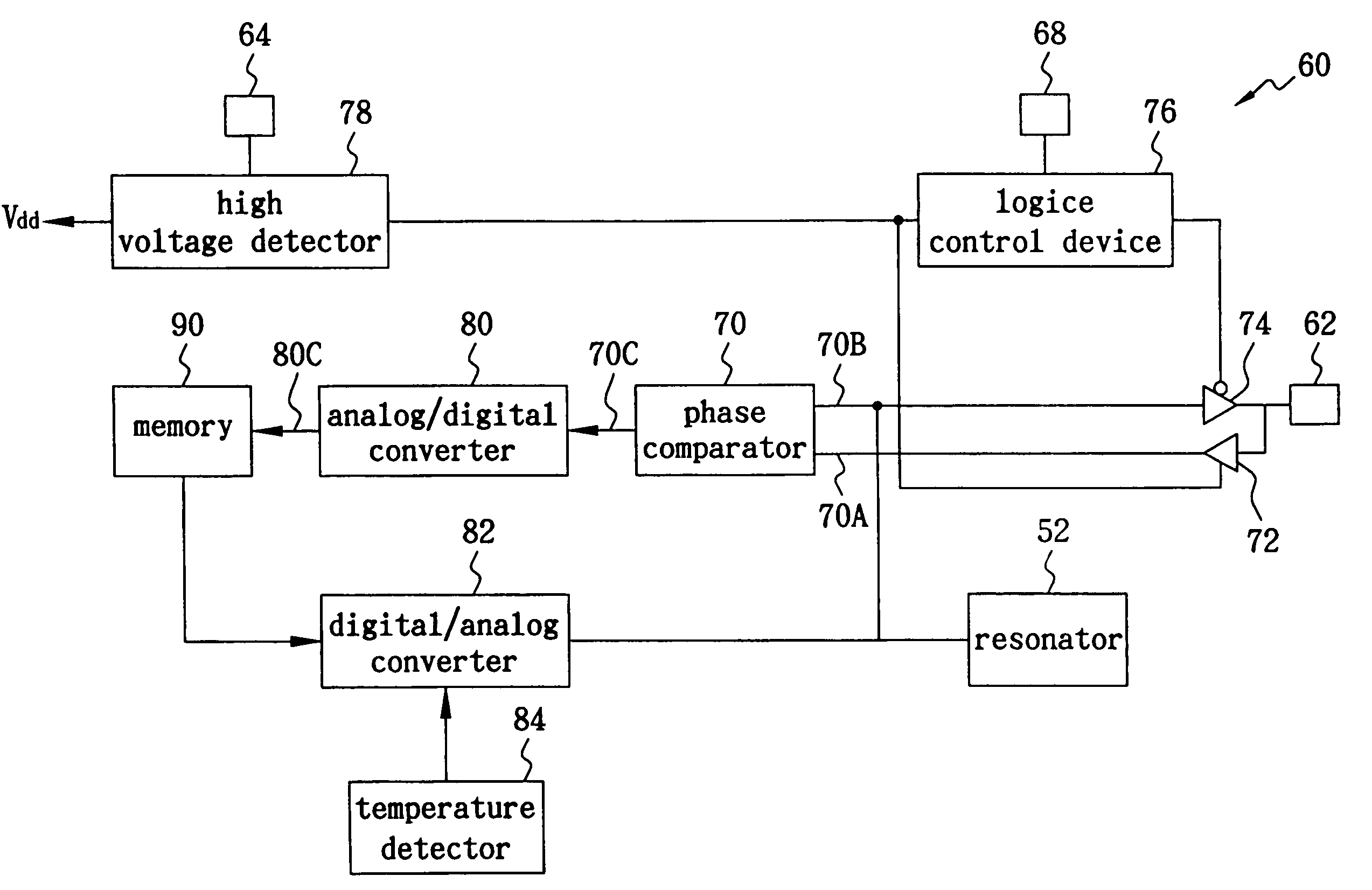
[0023]FIG. 4 is a functional block diagram of the integrated circuit 60 according to the present invention. As shown in FIG. 4, the integrated circuit 60 includes a phase comparator 70, an analog / digital converter 80 electronically connected to an output port 70C of the phase comparator 70, a memory 90 electronically connected to an output port 80C of the analog / digital converter 80, a digital / analog converter 82 electrically connected to the memory 90, and a temperature detector 84 ele...


PUM


Abstract

The present self-calibratable oscillating device includes a phase comparator, a clock pad electrically connected to a first input port of the phase comparator, a crystal oscillator electrically connected to a second input port of the phase comparator, an analog / digital converter electrically connected to an output port of the phase comparator, and a memory electrically connected to an output port of the analog / digital converter. The crystal oscillator can be a temperature-compensated crystal oscillator or a surface acoustic wave crystal oscillator. The present self-calibratable oscillating device can further includes a first switch positioned between the first input port of the phase comparator and the clock pad, a second switch positioned between the crystal oscillator and the clock pad wherein the stream direction of the first switch is in reverse of that of the second switch, and a logic control device for controlling the first switch and the second switch.

Description

RELATED U.S. APPLICATIONS[0001]Not applicable.STATEMENT REGARDING FEDERALLY SPONSORED RESEARCH OR DEVELOPMENT[0002]Not applicable.REFERENCE TO MICROFICHE APPENDIX[0003]Not applicable.FIELD OF THE INVENTION[0004]The present invention relates to an oscillating device, and more particularly, to a self-calibratable oscillating device, which can shorten the calibration time to lower the total test cost.BACKGROUND OF THE INVENTION[0005]Oscillating devices are generally applied to electronics that require a stable output frequency, such as mobile phones. Such oscillating device mostly incorporates an AT-cut crystal oscillator in a frequency band of 10 MHz as the oscillation source to constitute an oscillation circuit. Because the output frequency of the AT-cut crystal oscillator varies with the environmental temperature, it is necessary in practice to design a temperature compensation circuit for eliminating the frequency variation of the AT-cut crystal oscillator.[0006]FIG. 1 illustrates ...

Claims


Application Information

Patent Timeline
Patent Type & Authority Patents(United States)
IPC IPC(8): H03B5/32H03L1/02
CPCH03L1/026H03L1/025
Inventor YAO, CHUNG TING
Owner ELITE SEMICON MEMORY TECH INC
Why Eureka
Try Eureka