Calibration pattern for imaging device

a technology for imaging devices and calibration patterns, applied in the direction of electrical equipment, television systems, instruments, etc., can solve the problems of insufficient reduction of measurement errors and measurement errors of and achieve the effect of easy production of calibration patterns

Active Publication Date: 2011-12-22
MITUTOYO CORP
View PDF6 Cites 32 Cited by
  • Summary
  • Abstract
  • Description
  • Claims
  • Application Information

AI Technical Summary

Benefits of technology

[0029]The configuration above achieves functions and effects similar to those of the above-described calibration pattern. Furthermore, the simple spiral pattern allows easy production of the calibration pattern.

Problems solved by technology

With a small ratio of a distance between measurement edges relative to the vision field of the imaging device, the measurement error can not be sufficiently reduced due to aberration of a lens in the imaging device.
In this case, however, measuring a measured object having the light area measurement pattern or the dark area measurement pattern results in a measurement error of ±δ.

Method used


Image

  • Calibration pattern for imaging device
  • Calibration pattern for imaging device
  • Calibration pattern for imaging device

Examples


first embodiment

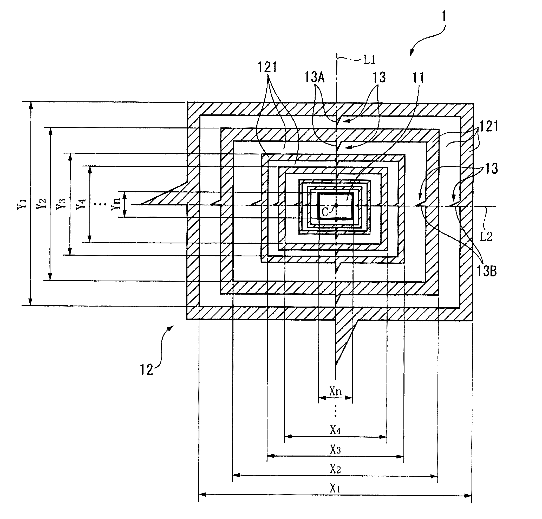
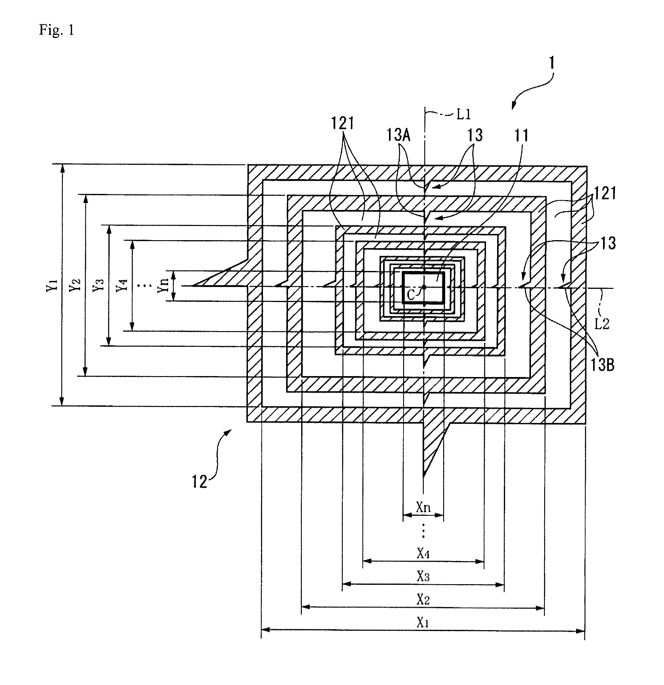
[0044]A first embodiment of the present invention is explained below with reference to the drawings. FIG. 1 illustrates a calibration pattern 1 according to the first embodiment of the present invention. In FIG. 1, a light area is indicated with a white area, and a dark area is indicated with a shaded area (the same applies hereinafter). The calibration pattern 1 is captured by an imaging device (not shown in the drawing) in order to correct the measurement error of the imaging device that measures a length of an object based on the captured image of the object. As shown in FIG. 1, the calibration pattern 1 has a central portion 11 and a frame pattern 12, the central portion 11 being provided with a rectangular light area in the central portion of the calibration pattern 1, the frame pattern 12 being provided outside the central portion 11.

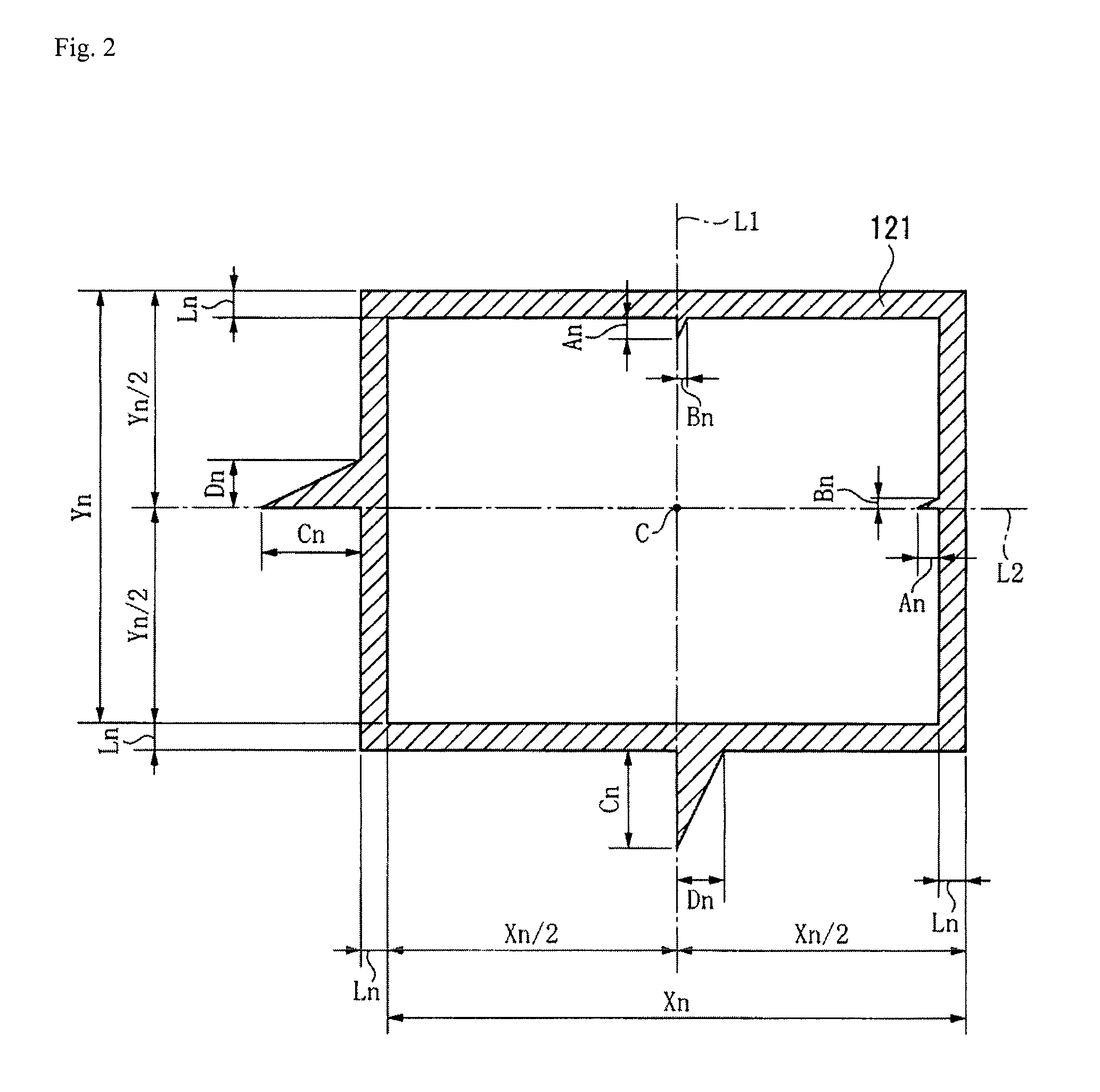
[0045]The frame pattern 12 has a plurality of frame portions 121 provided with rectangular frame-shaped light areas and dark areas, each of which...

second embodiment

[0064]A second embodiment of the present invention is explained below with reference to the drawings. The same reference numerals are provided below to the components explained above and the explanations thereof are omitted. FIG. 4 illustrates a calibration pattern 1A according to the second embodiment of the present invention. FIG. 5 illustrates a frame portion 121A provided with a dark area. In the first embodiment, the calibration pattern 1 has the central portion 11 provided with a rectangular light area and the plurality of frame portions 121 having a rectangular frame shape. The present embodiment is different, however, in that the calibration pattern 1A has a central portion 11A provided with a square light area and a plurality of frame portions 121A having a square frame shape, as shown in FIGS. 4 and 5.

[0065]In the first embodiment, the distances Xn and Yn between the edges are set based on the vision field sizes qn and pn of the imaging element of the imaging device, the p...

third embodiment

[0067]A third embodiment of the present invention is explained below with reference to the drawings. FIG. 6 illustrates a calibration pattern 1B according to the third embodiment of the present invention. In the embodiments above, the calibration patterns 1 and 1A each have the frame pattern 12, which includes the horizontal pattern and the vertical pattern. The present embodiment is different, however, in that the calibration pattern 1B has a swirl (or spiral) pattern 14, which includes a horizontal pattern and a vertical pattern, as shown in FIG. 6.

[0068]The calibration pattern 1B has the central portion 11 and the spiral pattern 14 provided outside the central portion 11. The spiral pattern 14 has two spiral portions 141 and 142 provided with a light area and a dark area, respectively, and formed into a spiral shape centering the central portion 11. The spiral portions 141 and 142 are provided in parallel to each other.

[0069]FIG. 7 illustrates the spiral portion 142 provided with...


PUM


Abstract

A calibration pattern is provided with a central portion and a frame pattern provided outside thereof, the central portion being provided with a rectangular light area in the central portion of the calibration pattern. The frame pattern has a horizontal pattern and a vertical pattern, the horizontal pattern extending to two horizontal sides centering the central portion and alternately provided with a light area and a dark area at a predetermined interval different from an equal interval, the vertical pattern extending to two vertical sides centering the central portion and alternately provided with a light area and a dark area at a predetermined interval different from an equal interval. The horizontal pattern and the vertical pattern include edges, each being positioned equally distant from a predetermined position in the central portion to the two sides, and the edges have an identical change direction of a gray value.

Description

CROSS-REFERENCE TO RELATED APPLICATIONS[0001]The present application claims priority under 35 U.S.C. §119 of Japanese Application No. 2010-137907 filed on Jun. 17, 2010, the disclosure of which is expressly incorporated by reference herein in its entirety.BACKGROUND OF THE INVENTION[0002]1. Field of the Invention[0003]The present invention relates to a calibration pattern for an imaging device, particularly a calibration pattern for an imaging device to be shot, or captured, by an imaging device to correct measurement error of the imaging device.[0004]2. Description of Related Art[0005]Conventionally known imaging devices include an image measurer and an optical device, the image measurer measuring a length of an object based on a captured image thereof. Such an imaging device captures a predetermined calibration pattern to correct measurement error. The calibration pattern is a combination of an area of a light image (hereinafter referred to as a light area) and an area of a dark i...

Claims


Application Information

Patent Timeline
Patent Type & Authority Applications(United States)
IPC IPC(8): H04N17/00
CPCG02B27/32
Inventor SHISHIDO, YUKO
Owner MITUTOYO CORP
Why Eureka
Try Eureka