Optical fiber structure and method of manufacturing same

a technology of optical fiber and fiber structure, which is applied in the direction of glass optical fiber, bundled fibre light guide, instruments, etc., can solve the problems of excessive stress received by optical fibers, unavailability of practical and inability to provide splittable coated optical fiber ribbons. , to achieve the effect of reducing the required tearing force, easy branched, and easy identification of splitting positions

Inactive Publication Date: 2009-03-24
TOMOEGAWA PAPER CO LTD
View PDF38 Cites 242 Cited by
  • Summary
  • Abstract
  • Description
  • Claims
  • Application Information

AI Technical Summary

Benefits of technology

[0040]In the optical fiber structure proposed by the present invention, multiple optical fiber units, each comprising multiple optical fibers that are aligned two-dimensionally in such a way that one side is covered by the first covering body, are aligned so that the covered surfaces face the same direction, and if the uncovered surfaces of these multiple optical fiber units are covered by the second covering body, the optical fiber units can be easily branched into individual units simply by splitting the optical fiber structure to branch the optical fibers by tearing the second covering body. This way, the splitting position can be identified very easily, and since the part to be torn is covered only with a single layer, the required tearing force can be minimized. Also, the optical fiber structure proposed by the present invention permits the optical fibers to be split within each optical fiber unit even after the second covering body has been torn, which facilitates the process of splitting optical fibers in the optical fiber unit. In addition, the optical fiber structure proposed by the present invention does not cause remnants of covering bodies to drop during the splitting process, thereby preventing such remnants from interfering with the connection process.
[0041]Furthermore, the method of manufacturing optical fiber structure proposed by the present invention allows for manufacture of an optical fiber structure by means of aligning and coating optical fibers and optical fiber units on a plane, without having to replace the application jig or using a special positioning jig, etc., as is the case under conventional manufacturing methods, whenever the number of optical fibers increases or decrease or other specification change occurs. Therefore, an optical fiber structure having a desired number of optical fibers can be manufactured simply and efficiently and the manufacturing cost can also be reduced. Also according to the method of manufacturing optical fiber structure proposed by the present invention, an optical fiber unit in which the alignment order of optical fibers is changed in a desired manner, with some optical fibers crossed, can be produced easily. Therefore, an optical fiber unit having optical fibers that have been wired in accordance with the I / O ports of the applicable device can be selectively used, and the efficiency of connecting optical fibers in accordance with the device I / O ports also improves significantly.
[0042]The optical fiber structure obtained by the manufacturing method proposed by the present invention can have the first covering body and second covering body adjusted to a uniform thickness and also provides excellent flexibility. Therefore, it can be used in practical applications such as wiring between devices.DETAILED DESCRIPTION OF THE PREFERRED EMBODIMENT
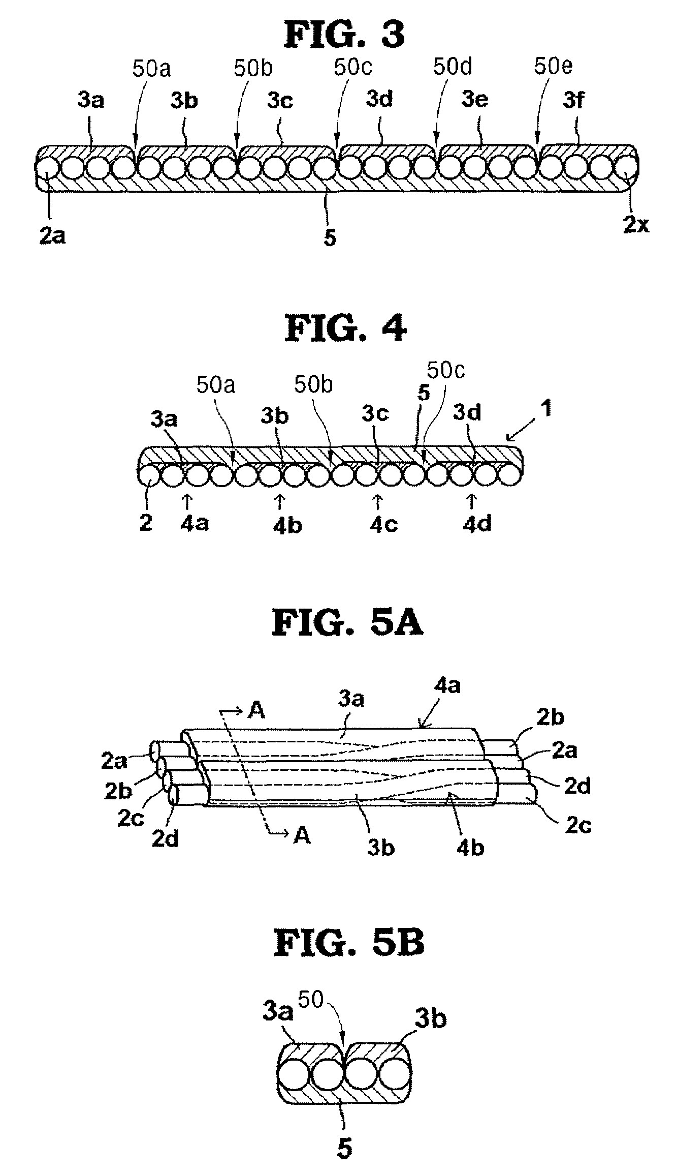
[0043]Embodiments of the optical fiber structure proposed by the present invention are explained below using drawings. In the present invention, “alignment” of optical fibers or optical fiber units means arranging and placing each optical fiber or each optical fiber unit in a desired position, where each adjacent pair of optical fibers may not have an equal distance or may cross with each other. Also, “aligned two-dimensionally” means arranging the target objects by placing them on a plane, and includes cases where optical fibers or optical fiber units are placed in a manner crossing with each other.
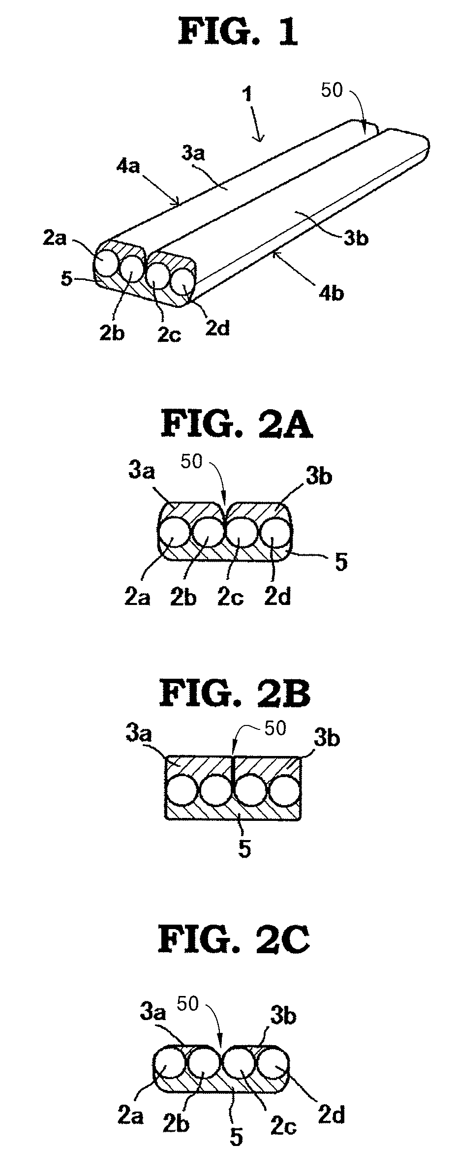
[0044]The first embodiment of the optical fiber structure proposed by the present invention has multiple optical fiber core wires aligned in parallel. FIG. 1 provides a perspective view of one example of this embodiment. In FIG. 1, the optical fiber structure is formed by two two-core optical fiber units, each comprising two optical fiber core wires. In FIG. 1, an optical fiber structure 1 is formed by an optical fiber unit 4a comprising aligned optical fiber core wires 2a and 2b, and an optical fiber unit 4b comprising aligned optical fibers 2c and 2d, where one side of the aligned optical fiber core wires of the optical fiber unit 4a is covered by a first covering body 3a, while one side of the aligned optical fiber core wires of the optical fiber unit 4b is also covered by a first covering body 3b. A groove 50 separates first covering body 3a and the first covering body 3b. These optical fiber units 4a and 4b are aligned in such a way that the covered surfaces face the same direction (top direction in the figure), while the surfaces not covered by the first covering body are integrally covered by a second covering body 5.
[0045]FIGS. 2A through 2C provide sectional views of an optical fiber structure having a similar structure to the one illustrated in FIG. 1, showing the various covering patterns of the first covering body over the optical fiber units. It is sufficient that the first covering body, which covers one side of the aligned multiple optical fiber core wires of each optical fiber unit, affixes the optical fiber core wires by means of covering. The representative covering pattern is one having the section structure shown in FIG. 2A, wherein a groove 50 is formed between the first covering body 3a and first covering body 3b. However, covering may be formed as shown in FIG. 2B, where the first covering bodies 3a and 3b of the two optical fiber units contact with each other comprising a groove 50 between them. Also, covering may be formed as shown in FIG. 2C, where the first covering bodies 3a and 3b cover the optical fiber core wires up to the tangential line common to the two circles defining the outer profiles of the two pairs of optical fiber core wires 2a and 2b, and 2c and 2d, constituting the respective optical fiber units.

Problems solved by technology

However, the process of splitting coated optical fiber ribbon manually or mechanically using a jig presents several problems, such as the need for a large force to split the optical fibers, generation of an excessive stress received by the optical fibers at the time of splitting, and easy occurrence of unnecessary splitting.
However, practical splittable coated optical fiber ribbons have not been provided so far.
Also, the method involving the use of a connection resin offering high peelability presents a new set of problems, such as contamination of surroundings and consequent interference with the connection process due to remnants of the connection resin layer peeling off at the time of splitting.
In the case of an optical fiber structure having a specific number of optical fibers and / or specific optical fiber pitch, therefore, a specific manufacturing apparatus prepared exclusively for the applicable conditions must be used to manufacture the optical fiber structure or the existing application jig must be replaced with a specific jig, which prevents efficient manufacture of an optical fiber structure having a desired number of optical fibers.

Method used


Image

  • Optical fiber structure and method of manufacturing same
  • Optical fiber structure and method of manufacturing same
  • Optical fiber structure and method of manufacturing same

Examples


example 1

[0079]The applicator shown in FIG. 20 was used to produce an optical fiber structure. This applicator comprised a single-axis control robot 11 and a material feeding apparatus 20, where the single-axis control robot had a board 6 on which to place optical fibers. A ball screw shaft 12 was placed along the longitudinal direction, and a drive motor 13 was provided at one end. The other end was supported by means of a bearing 14, and the ball bearing was screw-connected to a movable unit 15. This movable unit had a needle 16 for supplying material placed vertically to the stage surface. The needle was connected to the material feeding apparatus by a flexible rubber tube 17.

[0080]First, as shown in FIG. 20(a), four 30-cm long optical fibers 2a-2d (quartz single-mode fiber by Sumitomo Electric Industries; outer diameter 0.25 mm) were aligned in parallel on a board, and affixed with adhesive tape 21 near the ends. The needle (with an inner diameter of 1 mm) was affixed to the movable unit...

example 2

[0083]An eight-core, 1-m long optical fiber structure was produced using the same manufacturing method described in Example 1, except that thermosetting silicone rubber resin (TSE392 by GE Toshiba Silicone; tearing strength 5 kgf / cm) was used as the covering material for optical fibers on both sides. The covering material was cured by heating with a dryer for 1 hour using hot air of 120° C.

[0084]The optical fiber structure produced in this example exhibited excellent flexibility owing to the silicone rubber used as the covering material for aligned optical fibers, as well as good operability as a result of the bending flexibility during handling.

example 3

[0085]Twenty optical fiber units produced using the same method described in Example 1 were aligned in parallel to produce an eighty-core, 1-m long optical fiber structure in the same manner as in Example 1. Both the first covering body and second covering body were formed using room-temperature vulcanization silicone rubber (SE9186L by Toray Dow Corning).


PUM


Abstract

The present invention provides an optical fiber structure that allows for reliable and easy branching of optical fibers, as well as a method of manufacturing such optical fiber structure. The optical fiber structure proposed by the present invention is characterized by a structure wherein multiple optical fiber units, each comprising multiple optical fibers that are aligned two-dimensionally in such a way that one side is covered by a first covering body, are aligned so that the covered surfaces face the same direction, and the covered or uncovered surfaces of the multiple optical fiber units are integrally covered by a second covering body. The second covering body should preferably be made of silicone rubber having a tearing strength of 29 kgf / cm or below.

Description

BACKGROUND OF THE INVENTION[0001]1. Field of the Invention[0002]The present invention relates to an optical fiber structure that combines multiple optical fibers and is used for optical circuit packages, optical circuit devices and other applications pertaining to optical communication and optical information processing, as well as a method of manufacturing the same.[0003]2. Description of the Related Art[0004]An optical fiber structure is constituted by multiple optical fibers that are aligned and affixed to each other, and has the advantage of providing the smallest configuration for optical fiber core wiring. Traditionally, coated optical fiber ribbons have often been used as such optical fiber structures. For example, coated optical fiber ribbons are used to store multiple optical fibers in an optical fiber cable in a compact and dense manner, and they are also utilized for multi-core wiring of optical fibers between devices or within a single device.[0005]As the conversion of c...

Claims


Application Information

Patent Timeline
Patent Type & Authority Patents(United States)
IPC IPC(8): G02B6/44G02B6/04
CPCG02B6/4404G02B6/443G02B6/448G02B1/14G02B1/046G02B6/02395
Inventor SUZUKI, MASAYOSHISASAKI, KYOICHISUKEGAWA, KEN
Owner TOMOEGAWA PAPER CO LTD
Why Eureka
Try Eureka