Endoscope provided with an fibre optical bundle

a fiber optic bundle and endoscope technology, applied in endoscopes, medical science, surgery, etc., can solve the problems of light blocking and autoclaving, complex construction, manufacturing costs and maintenance expenditures, etc., to achieve high mechanical compliance, increase the number of illuminating sites, and easy branched

Inactive Publication Date: 2005-10-27
OLYMPUS WINTER & IBE
View PDF12 Cites 11 Cited by
  • Summary
  • Abstract
  • Description
  • Claims
  • Application Information

AI Technical Summary

Benefits of technology

[0008] The present invention provides a tapping system tapping light out of a fiber optics bundle and feeding it to a window in the outer endoscope wall, as a result of which, when the light source is ON, light travels from the window to the outside. In this manner, the endoscope is easily located even in darkness, without glare being present, thanks to the narrow dot of light. By using the light from the fiber optics bundle and because, thereby, additional light sources are not needed, problems are avoided regarding bulk and light blocking, as well as shortcomings regarding autoclaving that might arise when using additional light sources. Moreover, this feature circumvents complexity of construction, manufacturing costs and maintenance expenditures that would be entailed when using additional light sources. Again this feature allows central control of the emitted light at the light sources, for instance with respect to brightness or color.
[0010] The tapping system is in the form of optic fiber(s) branched from the fiber optics bundle and running to the window. This configuration again is economical regarding the number of parts used in the implementation of the principle of the present invention because the fiber optics bundle per se already consists of many optical fibers and individual fibers being easily branched off the bundle. Advantageously too, because of their high mechanical compliance, optical fibers may be made to move into endoscope regions that otherwise can be accessed only with difficulty for purposes of illumination. This ability exists only in limited form in other light sources such as LED's; moreover, and as already mentioned above, there might also be light-blocking and autoclaving problems. Again, this design principle allows increasing the number of illuminating sites almost arbitrarily and at low cost.
[0011] Additional features of the invention provide that the window shall be configured in the vicinity of the endoscope's functional elements or labelings. Such elements illustratively are shown by a light dot and in this manner are more easily located.
[0012] Advantageously, the features of the invention provide that the light issuing through the window illuminate endoscope functional elements or labelings. In this manner, the elements are more easily located and furthermore will be more easily handled or read.
[0013] Several tapping systems and windows are provided in the endoscope's external wall and by their configuration subtend a pattern of light dots. Illustratively, the main endoscope axes, the endoscope contour, or the connection cable receiving the proximal end of the light guide can be marked to facilitate rapidly and accurately locating, holding and putting down again of the endoscope or the hookup cable. In a similar manner, various endoscopes or their parts, for instance the grips, may be coded by simple light-dot patterns to allow rapid and reliable recognition and identification.

Problems solved by technology

Moreover, this feature circumvents complexity of construction, manufacturing costs and maintenance expenditures that would be entailed when using additional light sources.
This ability exists only in limited form in other light sources such as LED's; moreover, and as already mentioned above, there might also be light-blocking and autoclaving problems.

Method used


Image

  • Endoscope provided with an fibre optical bundle
  • Endoscope provided with an fibre optical bundle

Examples


Embodiment Construction

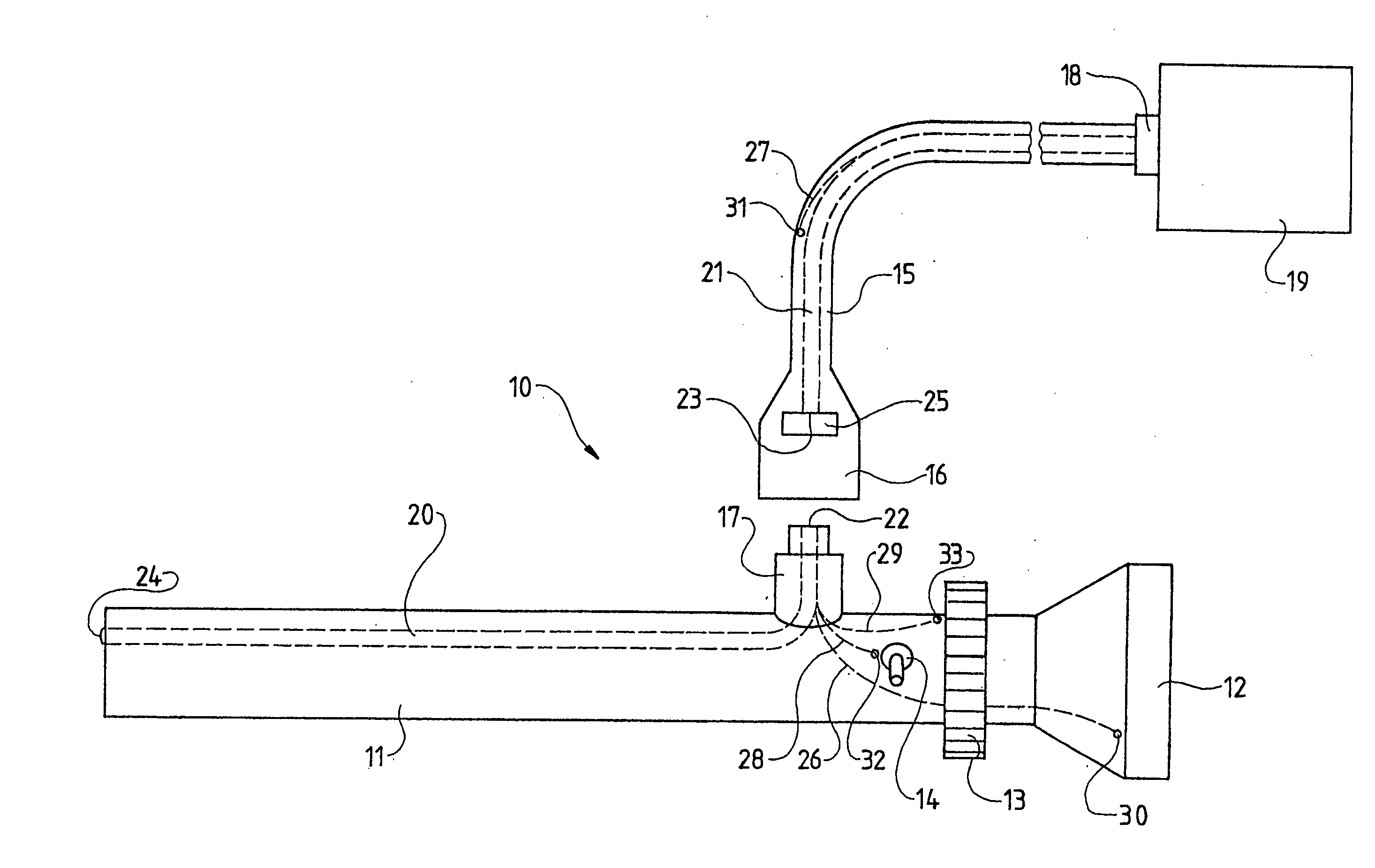
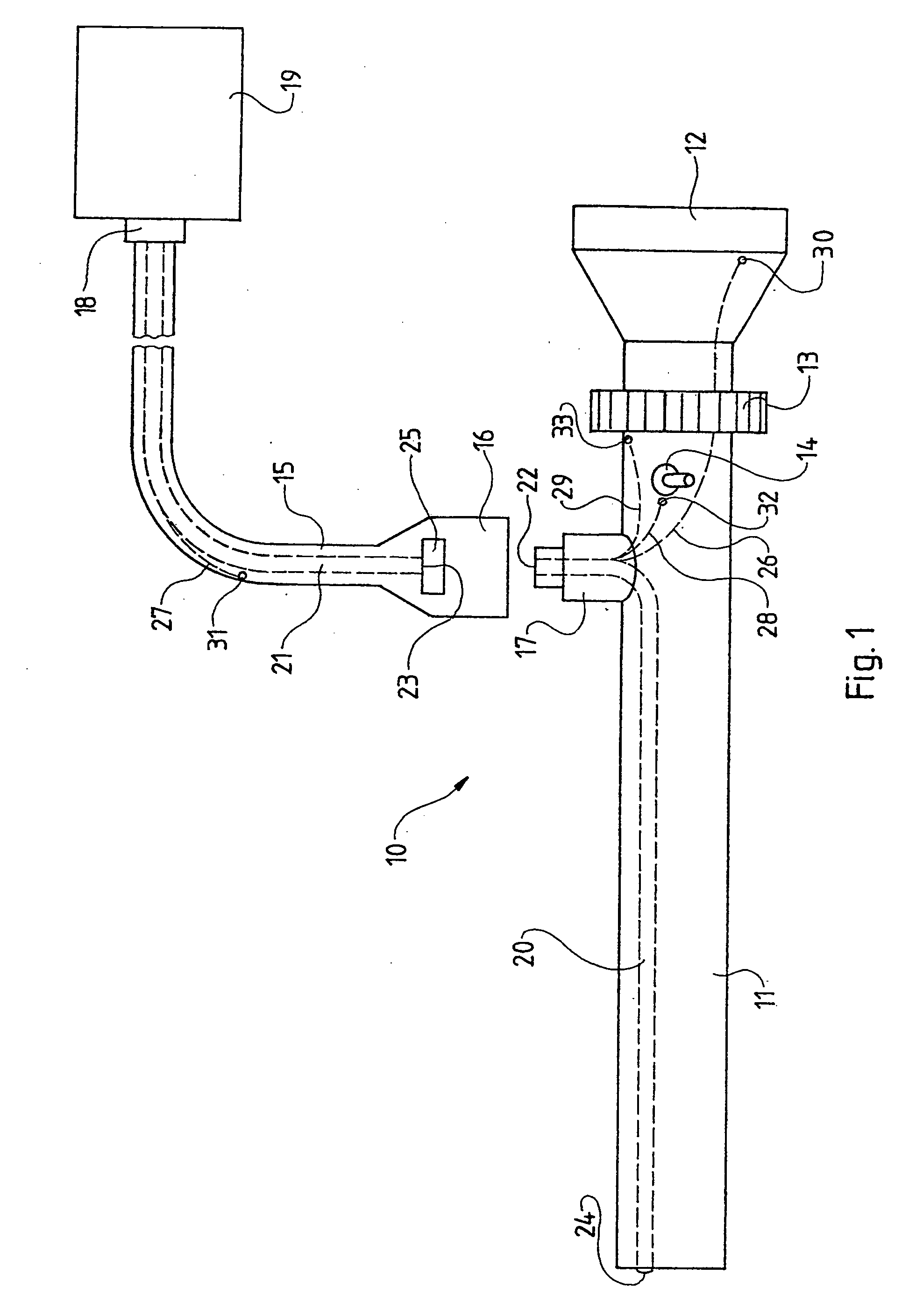
[0015]FIG. 1 shows an endoscope 10 of the present invention comprising a stem 11 which may be inserted into a body cavity, further an ocular 12, and an adjustment ring 13 and a switch 14. The endoscope 10 further comprises a fiber optics hookup cable 15 which can be connected by means of a coupling, (i.e. a jack 16) to another coupling, (i.e. a mating plug 17) on the stem 11 and—at its other end—by means of a coupling 18 to a light source 19. In FIG. 1, the fiber optics hookup cable 15 is shown disconnected from the plug 17. The endoscope 10 furthermore comprises a fiber optics bundle having a distal segment 20 and a proximal segment 21. The distal segment 20 of the fiber optics bundle runs in the stem 11 whereas the proximal segment 21 of the fiber optics bundle runs in the fiber optics hookup cable 15.

[0016] The proximal segment 21 of the fiber optics bundle guides the light from the light source 19 in the distal direction. The end faces 22 and 23 of the two fiber optics regions ...


PUM


Abstract

An endoscope including an image transmitting system and at least one fiber optics bundle which is mounted by its distal end segment in the endoscope and which at its distal end emits light to illuminate the field of view. A proximal end of the bundle is illuminated by a light source. The endoscope also includes, a tapping system for tapping light from the fiber optics bundle and guiding it to a window in the external endoscope wall.

Description

BACKGROUND OF THE INVENTION [0001] The present invention relates to an endoscope fitted with a fiber optical bundle, hereafter referred to as a fiber optics bundle. [0002] Foremost, such endoscopes are used in endoscopic surgery, in therapy, or diagnosis; they comprise a stem having a distal zone which can be inserted into an opening and a proximal zone which cannot be inserted in such an opening, furthermore, an image transmission system to view the field of observation, and a fiber optics bundle to illuminate the field of observation. [0003] The fiber optics bundle may be coupled to an external light source or be connected to a light source integrated into the endoscope. [0004] Conventionally, the image transmission system consists of an objective lens mounted on the stem end, relay lens elements and an ocular configured in a proximal zone. However, the relay lens elements may be replaced by a fiber optics bundle or an image transducing chip with their pertinent wires. The image t...

Claims


Application Information

Patent Timeline
Patent Type & Authority Applications(United States)
IPC IPC(8): A61B1/00A61B1/07
CPCA61B1/07A61B1/00167A61B1/00126
Inventor DIEKMANN, RALFMEINHARDT, GUNTHER
Owner OLYMPUS WINTER & IBE
Why Eureka
Try Eureka