[0040] In the optical fiber structure proposed by the present invention, multiple optical fiber units, each comprising multiple optical fibers that are aligned two-dimensionally in such a way that one side is covered by the first covering body, are aligned so that the covered surfaces face the same direction, and if the uncovered surfaces of these multiple optical fiber units are covered by the second covering body, the optical fiber units can be easily branched into individual units simply by splitting the optical fiber structure to
branch the optical fibers by tearing the second covering body. This way, the splitting position can be identified very easily, and since the part to be torn is covered only with a single layer, the required tearing force can be minimized. Also, the optical fiber structure proposed by the present invention permits the optical fibers to be split within each optical fiber unit even after the second covering body has been torn, which facilitates the process of splitting optical fibers in the optical fiber unit. In addition, the optical fiber structure proposed by the present invention does not cause remnants of covering bodies to drop during the splitting process, thereby preventing such remnants from interfering with the connection process.
[0041] Furthermore, the method of manufacturing optical fiber structure proposed by the present invention allows for manufacture of an optical fiber structure by means of aligning and
coating optical fibers and optical fiber units on a plane, without having to replace the application jig or using a special positioning jig, etc., as is the case under conventional manufacturing methods, whenever the number of optical fibers increases or decrease or other specification change occurs. Therefore, an optical fiber structure having a desired number of optical fibers can be manufactured simply and efficiently and the manufacturing cost can also be reduced. Also according to the method of manufacturing optical fiber structure proposed by the present invention, an optical fiber unit in which the alignment order of optical fibers is changed in a desired manner, with some optical fibers crossed, can be produced easily. Therefore, an optical fiber unit having optical fibers that have been wired in accordance with the I / O ports of the applicable device can be selectively used, and the efficiency of connecting optical fibers in accordance with the device I / O ports also improves significantly.
[0042] The optical fiber structure obtained by the manufacturing method proposed by the present invention can have the first covering body and second covering body adjusted to a uniform thickness and also provides excellent flexibility. Therefore, it can be used in practical applications such as wiring between devices. DETAILED DESCRIPTION OF THE PREFERRED EMBODIMENT
[0043] Embodiments of the optical fiber structure proposed by the present invention are explained below using drawings. In the present invention, “alignment” of optical fibers or optical fiber units means arranging and placing each optical fiber or each optical fiber unit in a desired position, where each adjacent pair of optical fibers may not have an equal distance or may cross with each other. Also, “aligned two-dimensionally” means arranging the target objects by placing them on a plane, and includes cases where optical fibers or optical fiber units are placed in a manner crossing with each other.
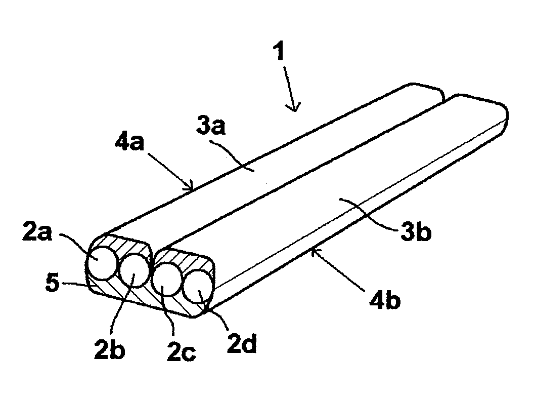
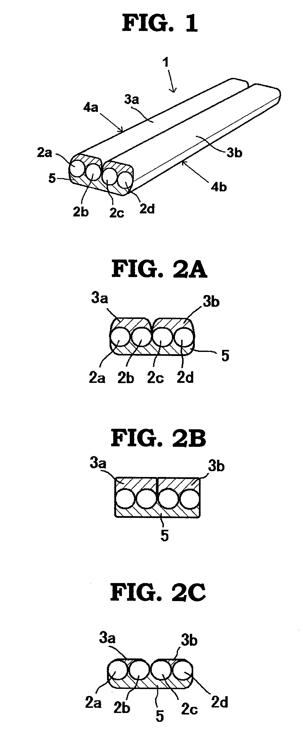
[0044] The first embodiment of the optical fiber structure proposed by the present invention has multiple optical fibers aligned in parallel. FIG. 1 provides a perspective view of one example of this embodiment. In FIG. 1, the optical fiber structure is formed by two two-
core optical fiber units, each comprising two optical fibers. In FIG. 1, an optical fiber structure 1 is formed by an optical fiber unit 4a comprising aligned optical fibers 2a and 2b, and an optical fiber unit 4b comprising aligned optical fibers 2c and 2d, where one side of the aligned optical fibers of the optical fiber unit 4a is covered by a first covering body 3a, while one side of the aligned optical fibers of the optical fiber unit 4b is also covered by a first covering body 3b. These optical fiber units 4a and 4b are aligned in such a way that the covered surfaces face the same direction (top direction in the figure), while the surfaces not covered by the first covering body are integrally covered by a second covering body 5.
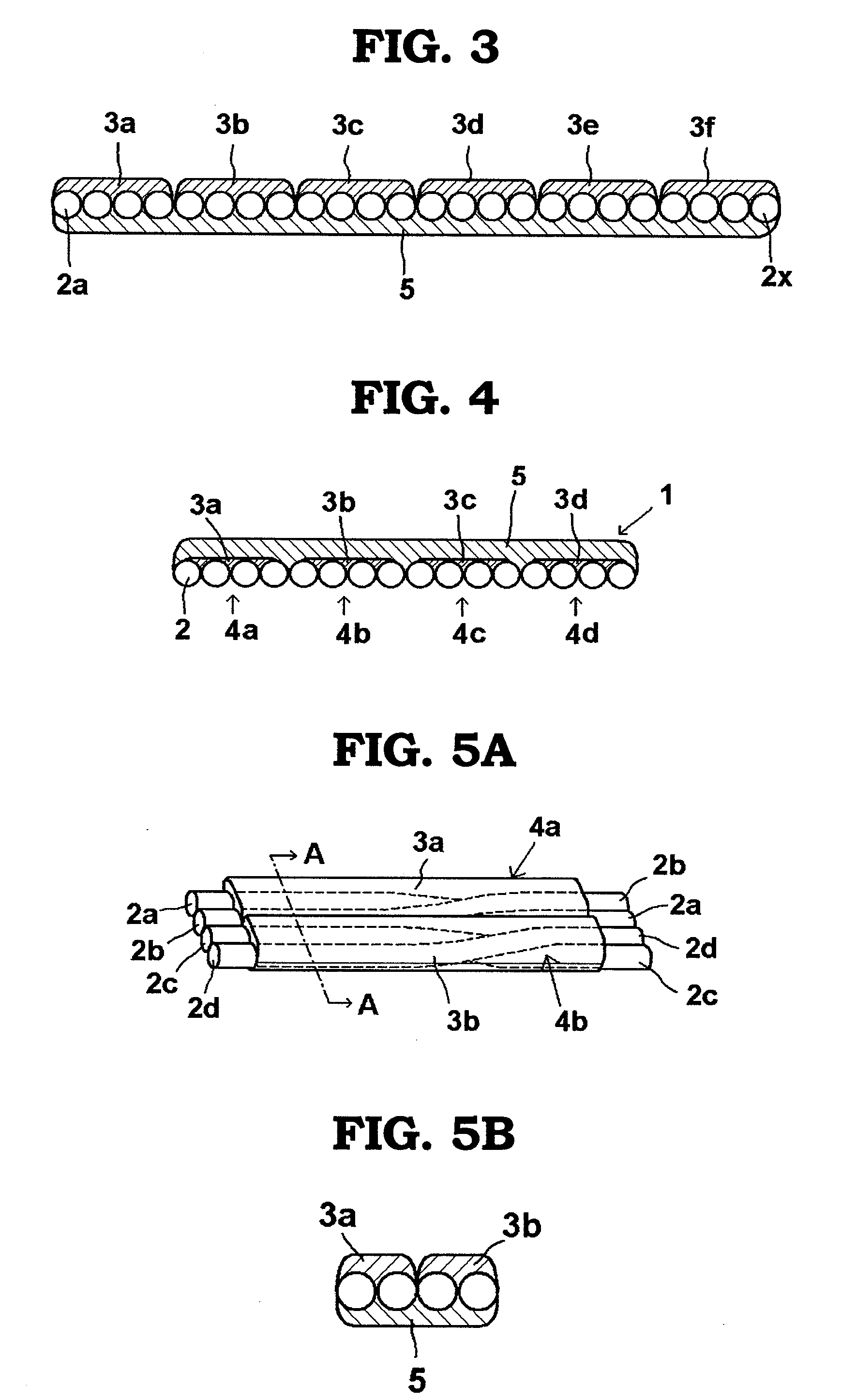
[0045]FIGS. 2A through 2C provide sectional views of an optical fiber structure having a similar structure to the one illustrated in FIG. 1, showing the various covering patterns of the first covering body over the optical fiber units. It is sufficient that the first covering body, which covers one side of the aligned multiple optical fibers of each optical fiber unit, affixes the optical fibers by means of covering. The representative covering pattern is one having the section structure shown in FIG. 2A, but covering may be formed as shown in FIG. 2B, where the first covering bodies 3a and 3b of the two optical fiber units contact with each other. Also, covering may be formed as shown in FIG. 2C, where the first covering bodies 3a and 3b cover the optical fibers up to the tangential line common to the two circles defining the outer profiles of the two pairs of optical fibers 2a and 2b, and 2c and 2d, constituting the respective optical fiber units.

