Method and system for generating three-dimensional model of part of a body from fluoroscopy image data and specific landmarks

a three-dimensional model and image data technology, applied in the field of three-dimensional model generation of a body part, can solve the problems of increasing radiation load on the patient and the operating staff, awkward purely fluoroscopic navigation, and corresponding radiation load on the patient and sta

Inactive Publication Date: 2006-01-05
BRAINLAB
View PDF16 Cites 232 Cited by
  • Summary
  • Abstract
  • Description
  • Claims
  • Application Information

AI Technical Summary

Benefits of technology

[0005] The present invention provides a method for generating a three-dimensional model of a part of the body that overcomes disadvantages of the prior art. In particular, the invention enables three-dimensional navigation using simple means without acquiring tomographs, specifically computer tomograph (CT) recordings, prior to performing the navigation. The invention can produce a three-dimensional model of a part of the body, thereby permitting navigation without successively obtaining new fluoroscopy recordings.
[0006] A method in accordance with the invention uses fluoroscopy image data sets in conjunction with positional identification of characteristic landmarks on a body part to generate a model of the body part. Combining fluoroscopy with positional identification of characteristic landmarks to generate the model of the part of the body results in much simpler and less elaborate calculations than using fluoroscopy image data sets alone.
[0007] The identified landmarks reproduce absolute spatial points which, in conjunction with fluoroscopic data, facilitate production of the model. In other words, the present invention combines two methods of detecting body features, each of which can be performed independently, in such a way so as to produce a three-dimensional model.

Problems solved by technology

This purely fluoroscopic navigation is awkward and often requires many x-ray recordings in order to obtain all the necessary data available at any desired point in time.
Additionally, the numerous x-ray recordings cause an increased radiation load on the patient and on the operating staff.
Using this technique, numerous x-ray recordings are taken in succession, which, like above, causes a corresponding radiation load on the patient and staff.

Method used


Image

  • Method and system for generating three-dimensional model of part of a body from fluoroscopy image data and specific landmarks
  • Method and system for generating three-dimensional model of part of a body from fluoroscopy image data and specific landmarks
  • Method and system for generating three-dimensional model of part of a body from fluoroscopy image data and specific landmarks

Examples


Embodiment Construction

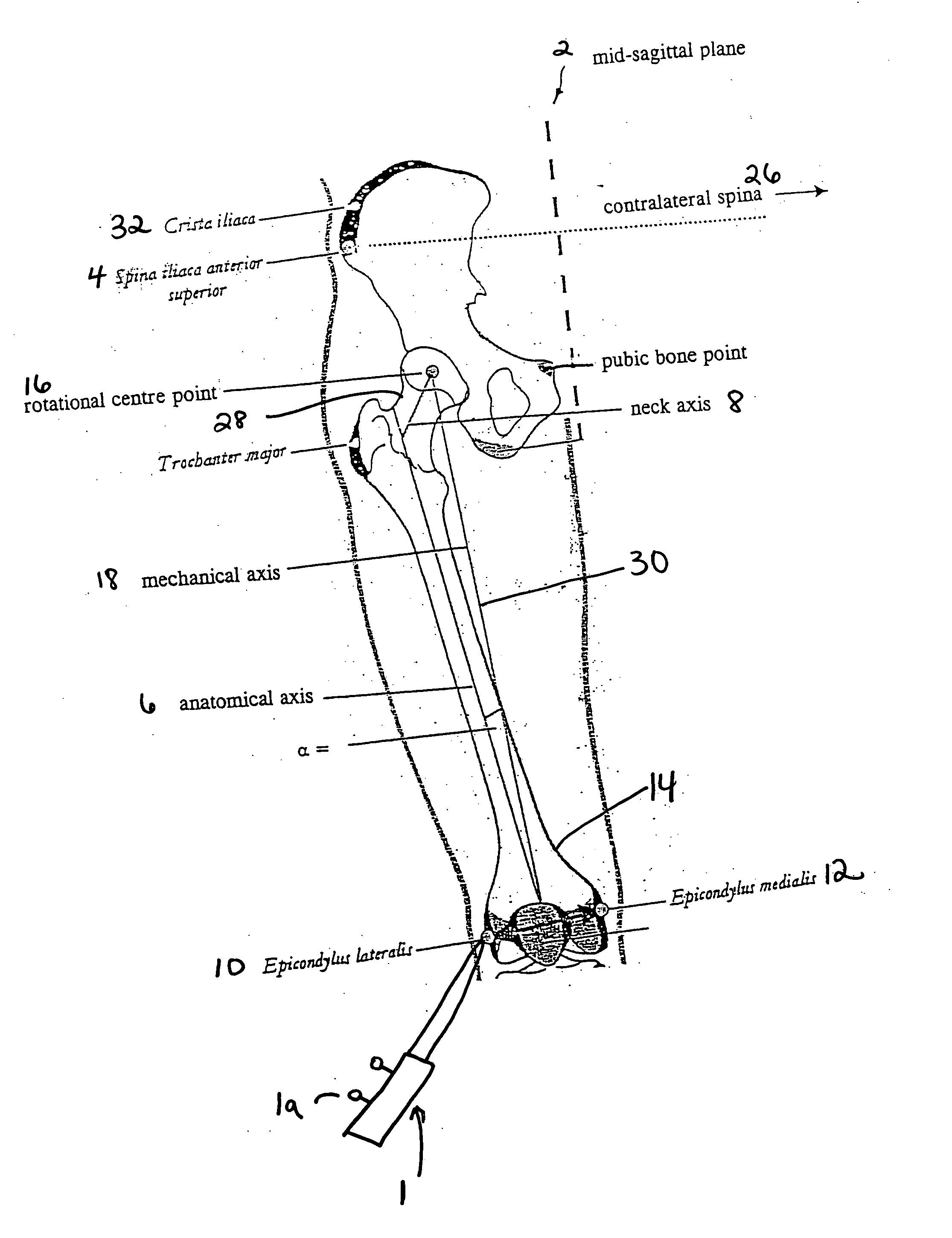
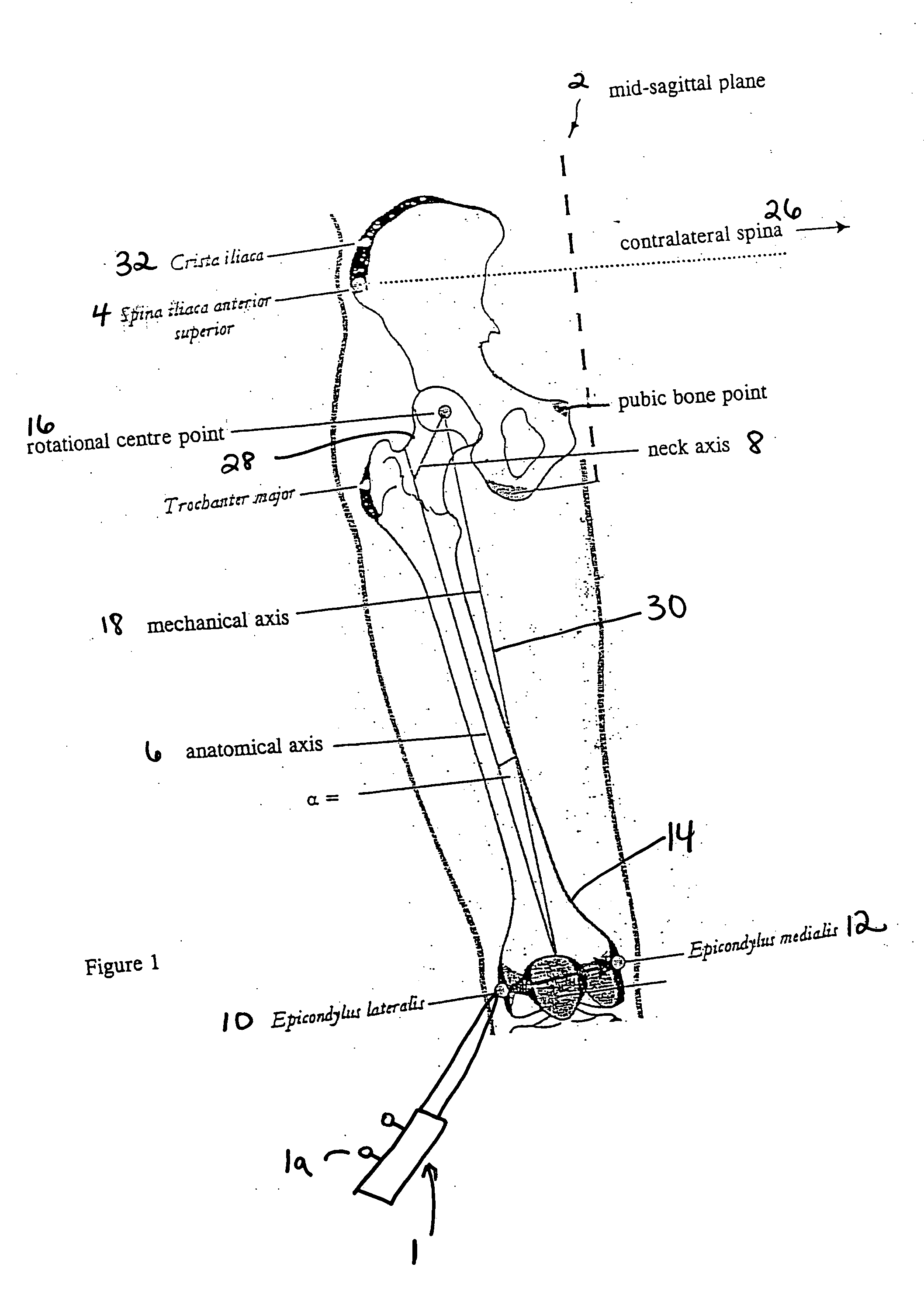
[0019] The invention will now be described in more detail on the basis of generating a model that can be used in hip operations. It should be appreciated, however, that the present invention can be applied to other medical procedures, and reference to hip operations is not intended to be limiting in anyway.

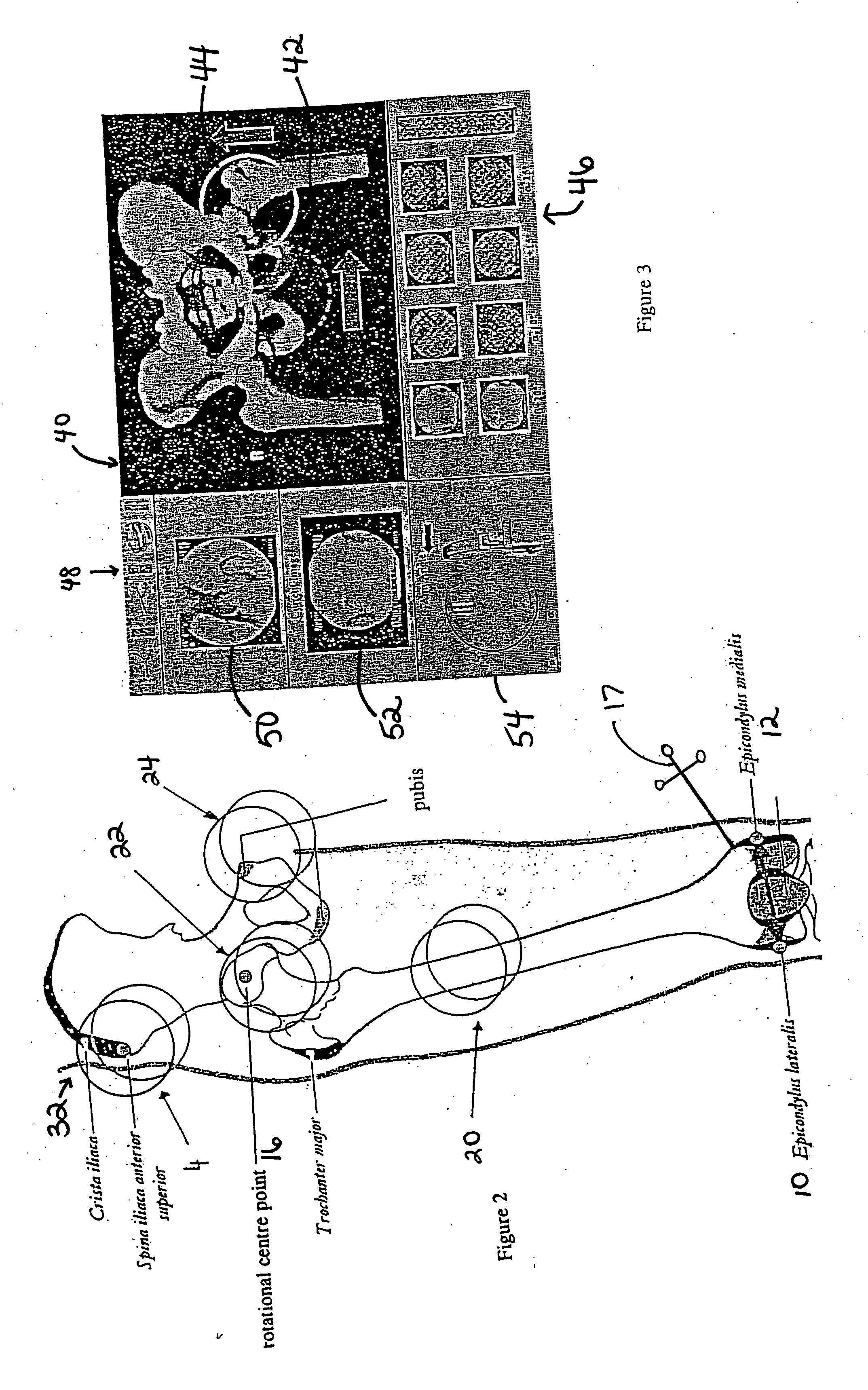
[0020] The invention provides a navigation method based on a three-dimensional model generated from two-dimensional fluoroscopic image recordings and specific landmarks of a part of the body. As a result, the three-dimensional orientation of the human pelvis is improved with respect to prior techniques, thereby enabling an implant to be suitably positioned in surgical total hip replacement procedures. This includes not only the hip bone but also the femur.

[0021] Two orientation parameters are important when positioning a cavity implant: the cavity anteversion and the cavity inclination. These two parameters relate to a hip coordinate system that is defined by the anatomy of the ...


PUM


Abstract

A method for generating a three-dimensional model of a part of the body with the aid of a medical and / or surgical navigation system, comprising the steps of identifying to the navigation system landmarks on the part of the body that are characteristic of the model of the part of the body; obtaining at least two fluoroscopy image data sets for each of one or more predetermined, individual and delimited regions of the part of the body; ascertaining characteristic body part data by processing and combining the landmark positions and parameters of the fluoroscopy data sets; and generating a three-dimensional and positionally determined model of the part of the body from the characteristic body part data.

Description

RELATED APPLICATION DATA [0001] This application claims priority of U.S. Provisional Application No. 60 / 588,898 filed on Jul. 16, 2004, which is hereby incorporated herein by reference in its entirety.FIELD OF THE INVENTION [0002] The present invention relates generally to a method for generating a three-dimensional model of a part of a body with the aid of a medical and / or surgical navigation system and, more particularly, to generating such a model without preceding tomographic imaging. BACKGROUND OF THE INVENTION [0003] Currently used techniques for computer tomographic-free navigation mainly involve navigation with the aid of x-ray images obtained from a fluoroscopy apparatus. Using the fluoroscopy apparatus, images are acquired and, after calibration and distortion correction, landmarks are determined in the images. This purely fluoroscopic navigation is awkward and often requires many x-ray recordings in order to obtain all the necessary data available at any desired point in ...

Claims


Application Information

Patent Timeline
Patent Type & Authority Applications(United States)
IPC IPC(8): A61B5/05
CPCA61B6/00A61F2002/3611A61B19/50A61B19/52A61B19/5244A61B2019/505A61B2019/5238A61B2019/5255A61B2019/5268A61B2019/5289A61B2019/5295A61F2/32A61F2/34A61F2/36A61B6/463A61B34/10A61B34/20A61B90/36A61B2034/105A61B2034/2055A61B2034/2068A61B2090/364A61B2090/367A61B2090/376
Inventor GRUNSCHLAGER, FRANKHAIMERL, MARTINLACHNER, RAINERVILSMEIER, STEFANRITTER, ALF
Owner BRAINLAB
Why Eureka
Try Eureka