Reduced pressure treatment system

a treatment system and pressure reduction technology, applied in the field of wound treatment, can solve the problems of pain, discomfort and pain for patients, separate expense sources of collection devices in the treatment of reduced pressure wounds, etc., and achieve the effects of reducing bacterial density, reducing pain, and improving healing speed

Active Publication Date: 2011-05-19
SMITH & NEPHEW INC
View PDF117 Cites 257 Cited by
  • Summary
  • Abstract
  • Description
  • Claims
  • Application Information

AI Technical Summary

Benefits of technology

[0026]In other embodiments, the method further comprises the step of placing tissue protection means on the tissue of the body that is to be approximately adjacent to the impermeable flexible overlay, such step being performed prior to positioning the impermeable flexible overlay over the area of the wound to be treated. The tissue protection means, which is described in more detail below, protects and strengthens the tissue of the body adjacent to the flexible overlay at the wound site. In yet other embodiments of the invention, the method further comprises the step of placing wound packing means (described in more detail herein) between the wound and the impermeable flexible overlay in the area of the wound to be treated, such step being performed prior to positioning the impermeable flexible overlay over the area of the wound to be treated. In still other embodiments, the reduced pressure under the impermeable overlay in the area of the wound is in the range from approximately 20 mm of Hg below atmospheric pressure to approximately 125 mm of Hg below atmospheric pressure. In still other embodiments, the reduced pressure is applied in a cyclic nature, the cyclic nature providing alternating time periods of application of reduced pressure and without application of reduced pressure.
[0027]In accordance with one embodiment, a treatment appliance is provided for treating a wound on a body by applying reduced pressure (i.e., pressure that is below ambient atmospheric pressure) to the wound in a controlled manner for a selected time period in a manner that overcomes the disadvantages of currently existing apparatus. For example, the application of reduced pressure to a wound provides such benefits as faster healing, increased formation of granulation tissue, closure of chronic open wounds, reduction of bacterial density within wounds, inhibition of burn penetration, and enhancement of flap and graft attachment. Wounds that have exhibited positive response to treatment by the application of negative pressure include infected open wounds, decubitus ulcers, dehisced incisions, partial thickness burns, and various lesions to which flaps or grafts have been attached.
[0028]In one embodiment, an appliance for treating a wound on a body is comprised of a cover, sealing means to seal the cover to the body, which are described in more detail below, and reduced pressure supply means, which are also described in more detail below. The cover, which is sized to be placed over and enclose the wound, is further comprised of a top cup member, an interface member, and interface attachment means for removably attaching the top cup member to the interface member. The interface member is further comprised of flow control means that permit exudate from the wound to flow from the wound into the top cup member, but not in the opposite direction. Thus, in this embodiment, the interface member is sealed to the body by the sealing means and exudate from the wound flows from the wound through the flow control means in the interface member into the volume of the cover above the interface member. The flow control means do not allow the exudate to flow back into the area of the wound under the interface member. The cover and the sealing means allow reduced pressure to be maintained in the volume under the cover at the site of the wound. The reduced pressure supply means operably connect the cover to a reduced pressure supply source that provides a supply of reduced pressure to the cover, so that the volume under the cover at the site of the wound is supplied with reduced pressure by the reduced pressure supply source.

Problems solved by technology

This collection device represents a separate source of expense in reduced pressure wound treatment.
If the treatment device is sealed to the body using an adhesive tape, removing the adhesive tape to monitor or treat the wound may cause discomfort and pain for the patient.
As tissue swelling in the area of the wound decreases during the healing process, the adhesive may begin to stretch the surrounding tissue, as well as tissue within the wound, resulting in discomfort and pain to the patient.
This may necessitate more frequent cover changes, increasing the time medical staff must expend in treating the wound.
This additional time, of course, also tends to increase the expense involved in treating the wound.
In addition, these types of covers can typically only be used where there is normal tissue adjacent to the wound to which the adhesive seal can be attached.
Otherwise, the seal must be made in a portion of the area of the wound, and exudate from the wound tends to break the seal so that reduced pressure cannot be maintained beneath the wound cover.
Further, the adhesive seal creates discomfort for the patient when the sheet cover is removed.
In these versions, the covers are sometimes difficult to use because the shape and contour of the patient's body in the area of the wound do not readily adapt to the shape of the cover.
This also increases the expense of wound treatment.
In these instances, the same disadvantages discussed above with respect to the first version also apply to this version as well.
Without the padding, the patient may experience pain and discomfort.
The additional padding, which may make the cover itself more expensive, may also take a greater amount of time to place on the patient for treatment purposes.
These covers may also have the problem of placing tension on the surrounding tissue as the swelling in the area of the wound decreases during the healing process.
This seal creates the same problems described above.
In addition, the same problems described above with respect to rigid and semi-rigid structures are also often present.
In all of the versions described above, it may be difficult to tell if reduced pressure in the area of the wound under the cover has been lost because the cover itself does not generally provide a visual clue of such loss.

Method used


Image

  • Reduced pressure treatment system
  • Reduced pressure treatment system
  • Reduced pressure treatment system

Examples


Embodiment Construction

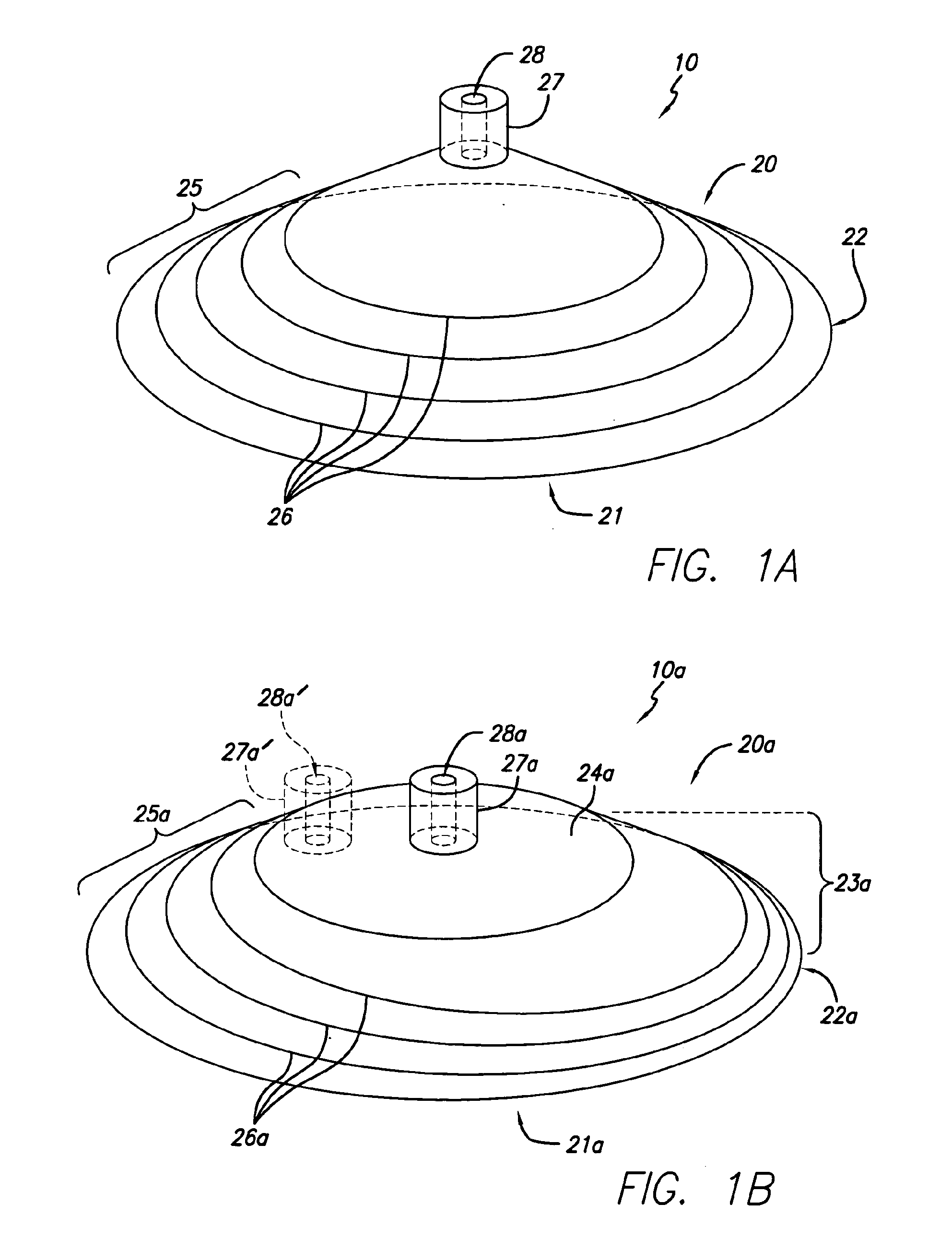
[0057]In accordance with one embodiment of the present invention, a wound treatment appliance is provided for treating all or a portion of a wound by applying reduced pressure (i.e., pressure that is below ambient atmospheric pressure) to the portion of the wound to be treated in a controlled manner for a selected time period in a manner that overcomes the disadvantages of currently existing apparatus. One embodiment is a wound treatment appliance 10 that is comprised of the fluid impermeable flexible overlay 20 illustrated in FIG. 1A and reduced pressure supply means, which are described in more detail below. In this embodiment, the flexible overlay 20 has an approximately elongated conical shape, having an opening 21 with an opening perimeter 22 adjacent to the opening 21 (at the base of the elongated conical shape) that is approximately elliptical in shape. The flexible overlay 20 illustrated in FIG. 1A is in its natural shape, as it exists prior to being applied to a patient for...


PUM


Abstract

A wound treatment appliance is provided for treating all or a portion of a wound. In some embodiments, the appliance comprises a cover or a flexible overlay that covers all or a portion of the wound for purposes of applying a reduced pressure to the covered portion of the wound. In other embodiments, the wound treatment appliance also includes a vacuum system to supply reduced pressure to the site of the wound in the volume under the cover or in the area under the flexible overlay. Methods are provided for using various embodiments of the invention.

Description

CROSS-REFERENCE TO RELATED APPLICATIONS[0001]This application is a continuation-in-part of U.S. application Ser. No. 12 / 719,715, filed on Mar. 8, 2010, which is a continuation of U.S. application Ser. No. 11 / 098,203, filed on Apr. 4, 2005, now U.S. Pat. No. 7,708,724, which claims the benefit of U.S. Application No. 60 / 559,727, filed on Apr. 5, 2004, each of which is incorporated herein by reference in its entirety. This application is also a continuation-in-part of U.S. application Ser. No. 11 / 064,813, filed on Feb. 24, 2005, which claims the benefit of U.S. Application No. 60 / 573,655, filed on May 21, 2004, each of which is incorporated herein by reference in its entirety. This application is also a continuation-in-part of U.S. application Ser. No. 11 / 098,265, filed on Apr. 4, 2005, which is a continuation-in-part of U.S. application Ser. No. 11 / 064,813, filed on Feb. 24, 2005, and which claims the benefit of U.S. Application No. 60 / 559,727, filed on Apr. 5, 2004, each of which is...

Claims


Application Information

Patent Timeline
Patent Type & Authority Applications(United States)
IPC IPC(8): A61M1/00
CPCA61F5/048A61M1/0088A61M1/0072A61M1/0056A61M1/0023A61M1/732A61M1/82A61M1/982A61M1/743A61M1/96A61M1/782A61M1/962A61M1/98A61F13/00068A61M1/79
Inventor WESTON, RICHARD SCOTT
Owner SMITH & NEPHEW INC
Why Eureka
Try Eureka