Arrangement for internal bone support

a bone support and arrangement technology, applied in the field of arrangement of internal bone support, can solve the problems of failure of fixation, relatively high failure rate, more complex procedure, etc., and achieve the effect of less complications, high tension, and faster healing

Inactive Publication Date: 2011-12-15
OZICS
View PDF7 Cites 66 Cited by
  • Summary
  • Abstract
  • Description
  • Claims
  • Application Information

AI Technical Summary

Benefits of technology

[0011]An advantage of the invention is that the fractured bone can be repositioned and fixed minimally invasive, meaning that only a small access opening is necessary to surgically perform an internal fixation, yet a structure persisting high tensional and torsional forces is achieved.
[0012]The technique allows the fixation of even large, load-bearing bones, without any additional implants or support structures.
[0013]Furthermore, minimally invasive surgery as opposed to open surgery has clear advantages for the patient and health care providers due to the fact that smaller wounds are produced that heal quicker with less complications and this gives opportunity to release the patients earlier from the hospital. It may also mean less pain for patient and lower cost for health care providers and insurance companies.
[0014]Compared to screw and plate fixation arrangements and alike, an advantage of the invention is that loads and stresses inside the bone are more evenly distributed when the invented arrangement is used. This leads to a better initial load-bearing capacity.
[0015]An inherent weakness of known screw and plate fixation arrangements is that stresses resulting from load bearing are typically concentrated proximally around the screw head and distally around the screw thread portions, often leading to failures of fixation in these areas. This is especially true when osteoporotic bones are fixed, because such bones possess a very weak internal bony structure where screws cannot be securely inserted with a sufficient purchase.
[0016]According to an embodiment of the invention the arrangement comprises further a filling material that is arranged to fill the normally occurring or artificially generated cavity where the expanded support device has been situated, the filling material adhering chemically or physically to the support device. An advantage is that a solid construction supporting the fracture site well is generated as the consequence of the curing or hardening of the filling material.

Problems solved by technology

This is an even more complex procedure which is usually chosen if fracture fixation devices would not provide enough stability of the bone due to poor bone quality and insufficient purchase of screws in the bone, or in case there are some other reasons for a more thorough repair, such as osteoarthritis.
If fracture fixation devices are chosen to stabilize the femur, such a fixation is associated with a relatively high failure rate as full immediate load bearing on the joint is not allowed and premature loading will lead to failure of the fixation and will necessitate a reoperation.
Due to the insufficient primary stability of the bone after fracture fixation for the first 6-12 weeks after surgery, patients are forced to rest in bed for extended periods, first in the hospital where the surgery took place and thereafter in a rehabilitation clinic.
Currently, about 60% of all hip fractures occur as a result of osteoporosis, a disease that affects bone density and makes them very susceptible to fractures.
Even low impact falls may lead to fractures in the hip, typically in the proximal part of femur.
Especially in the elderly who represent the majority of osteoporotic patients, this prolonged bed-rest together with their pre-existing other medical pathologies lead to other medical problems which substantially drive up the mortality and morbidity rates.

Method used


Image

  • Arrangement for internal bone support
  • Arrangement for internal bone support
  • Arrangement for internal bone support

Examples


Embodiment Construction

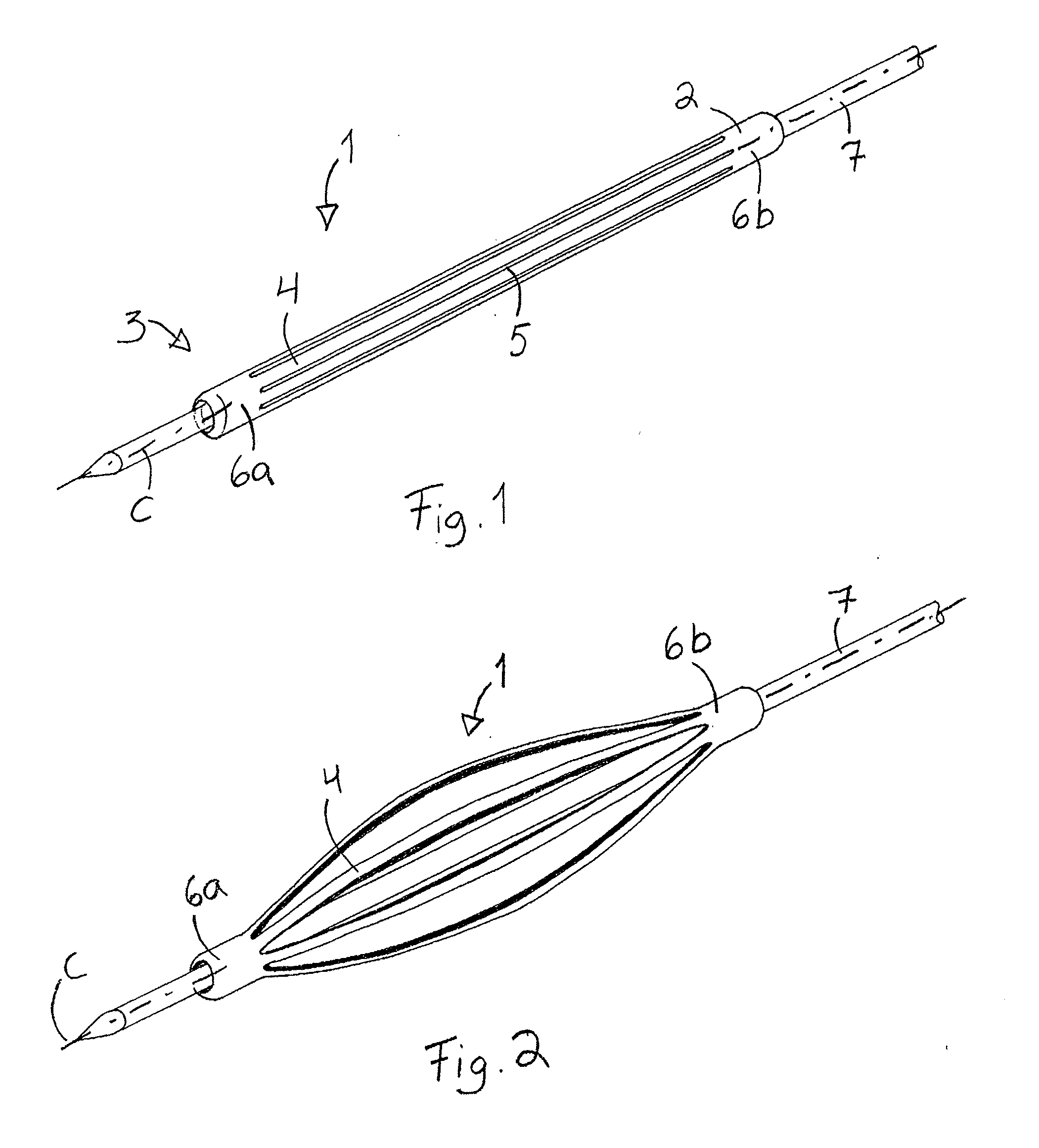
[0043]FIG. 1 is a schematic perspective view of a support device according to the invention in a reduced configuration, and in FIG. 2 in its expanded configuration.

[0044]The support device 1 in its reduced configuration comprises an expandable frame 2 that has an oblong tube-like shape having a longitudinal channel 3 therethrough. The cross section of the frame 2 is round and its diameter is constant essentially along its entire length. The imaginary longitudinal centre line of the frame 2 is depicted by reference symbol “C”.

[0045]It is to be noted here that the cross section of the frame 2 may also be angulated or oval etc.

[0046]The frame 2 comprises a number of strips 4 that are arranged longitudinally, i.e. they are arranged at least substantially parallel with the longitudinal centre line C and the channel 3. The number of the strips 4 is preferably 2 to 100, more preferably 4 to 12, most preferably 6 to 8.

[0047]A strip 4 is separated from the next one by a slit 5 which extends ...


PUM


Abstract

An arrangement for internal bone support. The arrangement includes a support device insertable in a cavity of the bone to be supported. The support device includes a frame having first and second end sections, the frame including a plurality of longitudinally arranged strips. The frame is capable to expand from a reduced configuration to an expanded configuration in a direction perpendicular to the longitudinal centre line of the frame.

Description

CROSS-REFERENCE TO RELATED APPLICATIONS[0001]The present application claims the benefit of priority to European Patent Application No. 09169027.1, filed 31 Aug. 2009, the contents of which are incorporated herein by reference in their entirety.FIELD OF THE INVENTION[0002]The present invention relates to an arrangement for internal bone support.BACKGROUND OF THE INVENTION[0003]When a bone fractures, it is immobilized by external or internal fixation in order to give the bone opportunity to build new callus and heal so it can again carry the intended loads. External fixation is accomplished by the use of a plaster cast, or in more complex scenarios, by use of external fixation devices, e.g. scaffolds outside the body that keep the bone in the right position. Internal fixation is typically achieved by means of screws, plates, intramedullary nails, wires, cables, or combination thereof, herein referred to as fracture fixation devices.[0004]For example fractures in the proximal femur are...

Claims


Application Information

Patent Timeline
Patent Type & Authority Applications(United States)
IPC IPC(8): A61B17/58
CPCA61B17/164A61B17/1668A61B17/7097A61B17/7098A61B17/7258A61B2019/5483A61B17/742A61B17/744A61B17/848A61B17/8858A61B17/7275A61B2090/3983
Inventor KAIKKONEN, AUVOP+E,UML O+EE SEL, ANDREAS
Owner OZICS
Why Eureka
Try Eureka