Developing device and image forming apparatus

a technology of developing device and image forming apparatus, which is applied in the direction of electrographic process apparatus, instruments, optics, etc., can solve the problems of image defect such as white stripes, easy coagulation of toner, and serious problems of toner coagulation, and achieve the effect of wasting toner

Inactive Publication Date: 2007-09-06
SHARP KK
View PDF5 Cites 3 Cited by
  • Summary
  • Abstract
  • Description
  • Claims
  • Application Information

AI Technical Summary

Benefits of technology

[0049]According to the invention, the use of the above-described developing device as a developing section in an electrophotographic image forming apparatus comprising a photoreceptor drum, a charging section, an exposing section, a developing section, a transfer section, and a fixing section leads drastic reduction in wasteful consumption of the toner, thus resulting in an image forming apparatus by which high-quality images having no image defects such as white stripes can be formed for a long period of time and of which developing device only needs less-frequent facilitated maintenances.

Problems solved by technology

The non-magnetic one-component developing device has a problem that a toner is more easily coagulated compared to the case of using a two-component developer containing a toner and a magnetic carrier.
Especially in a contact portion between the developing roller and the doctor blade, the toner coagulation causes a serious problem.
The fused toner adhered to the doctor blade scrapes the toner layer on the developing roller, which contacts the toner-adhered part, thus causing an image defect such as white stripes.
Accordingly, the toner-adhered part grows in size over time and thereby gives flaws to the surface of developing roller, with the result that a service life of the apparatus itself may possibly be shortened.
The techniques disclosed in JP-A 62-86381 (1987) and JP-A 2001-194896 cannot, however, sufficiently prevent the toner from undergoing the fusion and adhesion because an image forming apparatuses of date uses a toner having a relatively low melting point.
However, the fusion and adhesion of toner easily occur also on a surface of the doctor blade positioned at downstream side of the rotation direction of the developing roller, and actually in many cases, the fusion and adhesion of toner occurring on the downstream surface is massive.
Another problem of JP-A 58-150984 (1983) is risk that the pressing member sliding in parallel with the surface of the doctor blade might cause the toner to be caught between the pressing member and the rubbing surface of the doctor blade, resulting in the toner adhesion over an entire surface of the doctor blade.

Method used


Image

  • Developing device and image forming apparatus
  • Developing device and image forming apparatus
  • Developing device and image forming apparatus

Examples


first embodiment

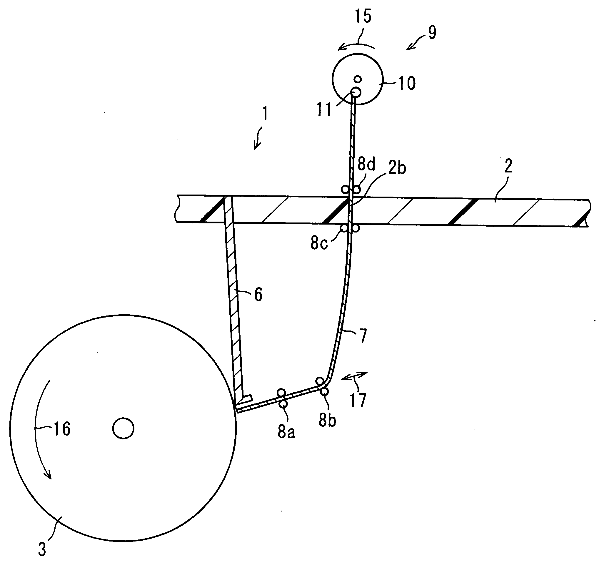
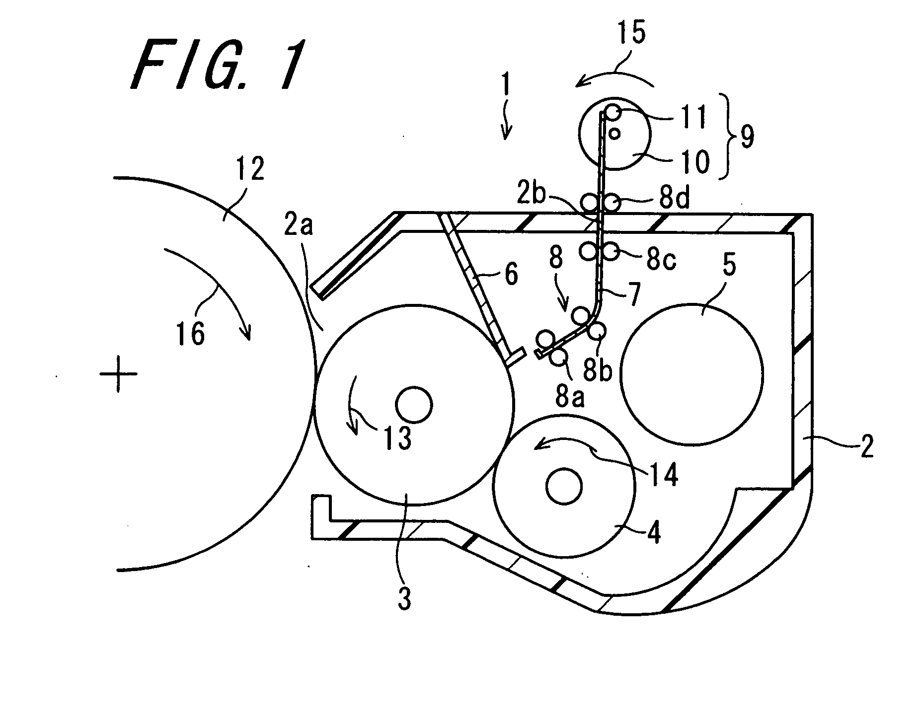
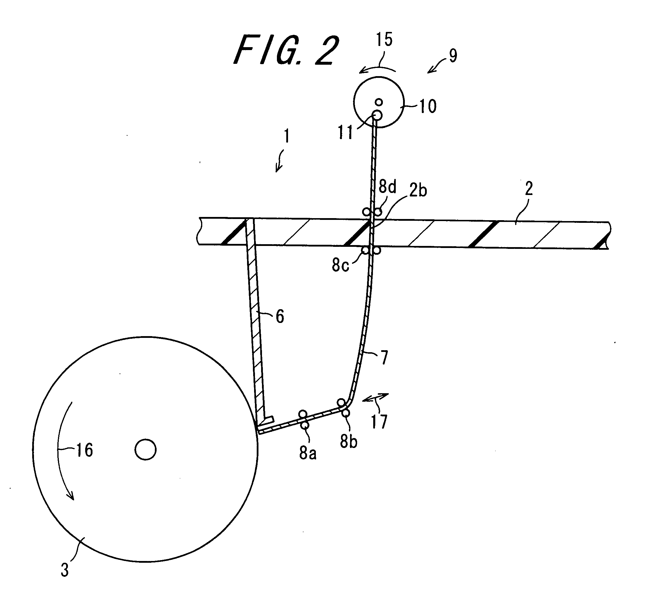
[0059]FIG. 1 is a sectional view schematically showing a configuration of a developing device 1 according to the invention. In FIG. 1, a cleaning member 7 is away from a doctor blade 6. FIG. 2 is a sectional view showing a developing device 1 shown in FIG. 1, in which the cleaning member 7 is in contact with the doctor blade 6. The developing device 1 is provided in an electrophotographic image forming apparatus and forms a toner image by supplying a toner to an electrostatic latent image formed on a surface of a photoreceptor drum 12, thus conducting development. The developing device 1 includes a developer tank 2, a developing roller 3, a supply roller 4, a stirring member 5, the doctor blade 6, the cleaning member 7, a supporting section 8, and a driving mechanism 9.

[0060]The developer tank 2 is a container-shaped member formed of, for example, hard synthetic resin. In an interior space of the developer tank 2 are contained the developing roller 3, the supply roller 4, the stirri...

second embodiment

[0071]FIG. 3 is a sectional view schematically showing a configuration of chief part of a developing device 20 according to the invention. The developing device 20 is similar to the developing device 1, and corresponding parts will be denoted by the same reference numerals to omit descriptions thereof, or alternatively, illustrations of the corresponding parts will be omitted. The developing device 20 is characterized by a doctor blade 21 with which the doctor blade 6 in the developing device 1 is replaced. The doctor blade 21 is an elongated platy member which extends in parallel with the axial line of the developing roller 3 and of which sectional shape is formed into an inverted Y shape in a direction perpendicular to the axial direction of the developing roller 3. That is to say, the doctor blade 21 is formed of thin plates made of an elastic metal material such as stainless steel, and formed in such a manner that two elongated rectangular thin plates are bonded to each other on...

third embodiment

[0072]FIG. 4 is a sectional view schematically showing a configuration of chief part of a developing device 23 according to the invention. The developing device 23 is similar to the developing device 1, and corresponding parts will be denoted by the same reference numerals to omit descriptions thereof, or alternatively, illustrations of the corresponding parts will be omitted. The developing device 23 is characterized by a cleaning member 24 with which the cleaning member 7 in the developing device 1 is replaced. The cleaning member 24 is characterized in its free end portion, i.e., a tip 25 which is formed into a brush shape. It is possible to implant brush bristles directly in the tip 25. The brush bristles are formed into a stripe shape, a columnar shape, etc., and implanted as in the case of a commonly-available brush bristles, including in a radial pattern or in a linear pattern composed of plural arrays. Further, a brush-shaped member may be coupled to the tip 25. In any case,...


PUM


Abstract

A developing device includes a developer tank, a developing roller, a supply roller, a stirring member, and a doctor blade. The developing device is provided with: a cleaning member detachably provided on a contact portion of the doctor blade with the developing roller, which slides to rub a surface of the doctor blade upon contacting; a supporting section for supporting the cleaning member so as to be capable of being attached to and detached from the contact portion of the doctor blade with the developing roller; and a driving mechanism for moving the cleaning member so as to be attached to and detached from the contact portion of the doctor blade with the developing roller.

Description

CROSS-REFERENCE TO RELATED APPLICATION[0001]This application claims priority to Japanese Patent Application No. JP 2006-58243, which was filed on Mar. 3, 2006, the contents of which, are incorporated herein by reference, in their entirety.BACKGROUND OF THE INVENTION[0002]1. Field of the Invention[0003]The present invention relates to a developing device and an image forming apparatus.[0004]2. Description of the Related Art[0005]An electrophotographic system, which enables easy formation of high-quality images at relatively low-cost, has been widely adopted into image forming apparatuses such as a copier, a printer, and a facsimile. An electrophotographic image forming apparatus comprises: for example, a photoreceptor drum of which surface is provided with a photosensitive layer containing a photoconductive substance; a charging section for charging the surface of photoreceptor drum; an exposing section for exposing the surface of photoreceptor drum being charged, to form thereon an ...

Claims


Application Information

Patent Timeline
Patent Type & Authority Applications(United States)
IPC IPC(8): G03G15/08
CPCG03G15/0812
Inventor INOUE, ATSUSHIKAZAKI, YUICHIYAMANAKA, TAKAYUKINAKAYA, HIROAKI
Owner SHARP KK
Why Eureka
Try Eureka