Image forming apparatus

a technology of forming apparatus and forming roller, which is applied in the direction of electrographic process apparatus, instruments, corona discharge, etc., can solve the problems of inconvenient configuration of developing roller and photosensitive drum after completion of apc, inability to stabilize laser beam amount, and inability to develop, etc., to achieve shorten the first print out time (fpot) and prevent wasteful toner consumption

Active Publication Date: 2013-05-02
CANON KK
View PDF6 Cites 14 Cited by
  • Summary
  • Abstract
  • Description
  • Claims
  • Application Information

AI Technical Summary

Benefits of technology

[0011]The present disclosure relates to an image forming apparatus capable of not only shortening first print out time (FPOT) but also preventing wasteful toner consumption in an easy way.

Problems solved by technology

For example, a laser beam printer using a laser beam as an exposure device has a problem of the stabilization of the laser beam amount.
Therefore, if the developing roller contacts the photosensitive drum during execution of the APC, toner may be uselessly consumed (developed).
Therefore, the conventional configuration in which the developing roller contacts the photosensitive drum after completion of APC is not desirable because of an increase in FPOT.
In other words, irradiation of an identical laser beam amount does not necessarily provide the same potential on the photosensitive drum.
Such variation in the photosensitive drum sensitivity may produce a potential difference between the photosensitive drum and the developing roller causing toner movement therebetween, possibly resulting in wasteful toner consumption.

Method used


Image

  • Image forming apparatus
  • Image forming apparatus
  • Image forming apparatus

Examples


Embodiment Construction

[0041]Various exemplary embodiments, features, and aspects of the invention will be described in detail below with reference to the drawings.

[0042]An image forming apparatus according to the present invention will be described in more detail below with reference to the accompanying drawings.

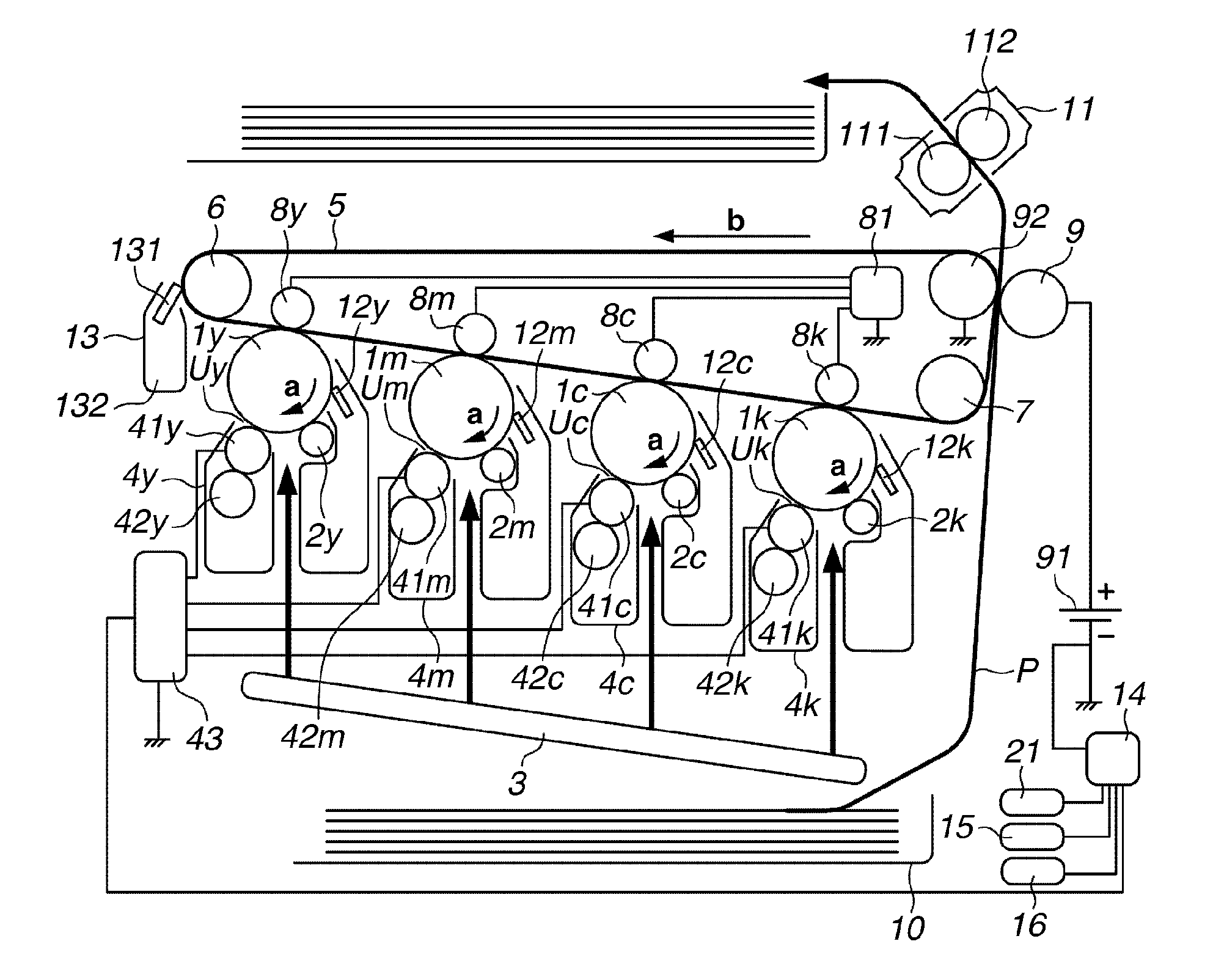
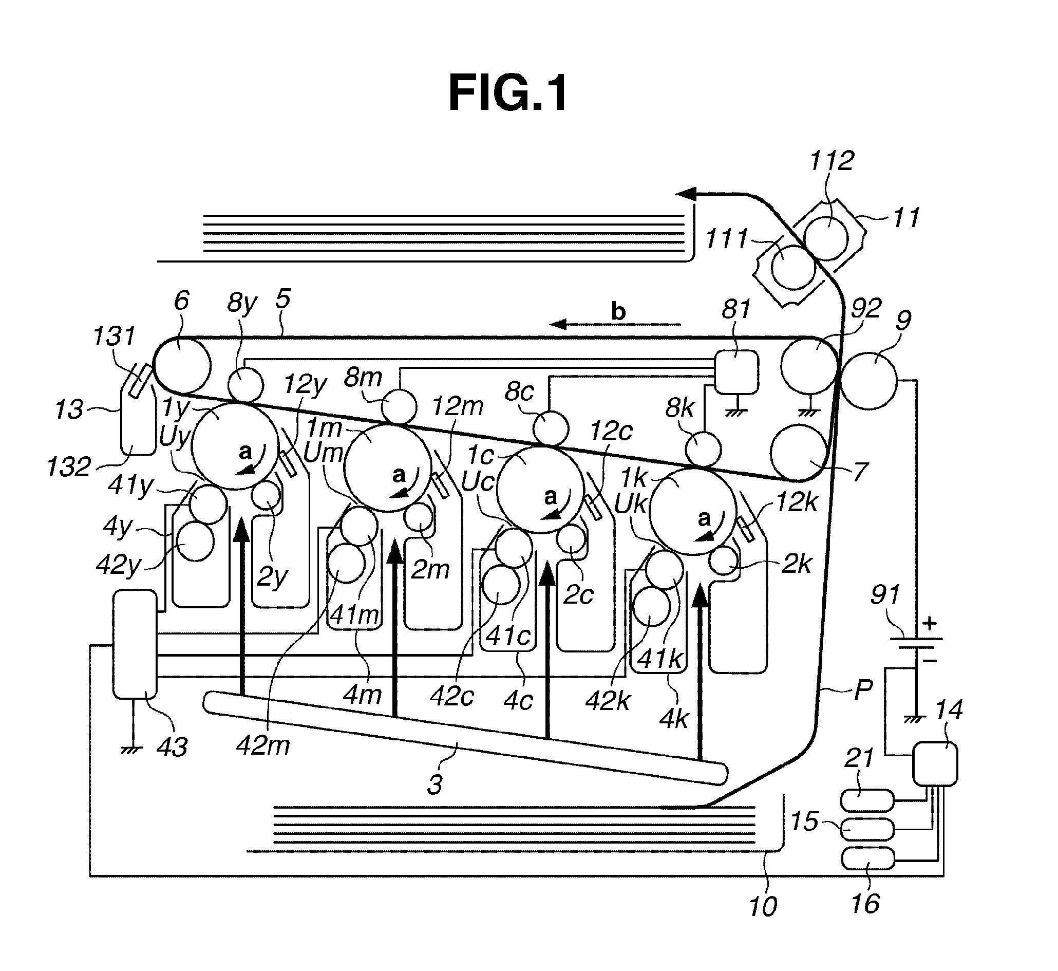
[0043]FIG. 1 illustrates an overall configuration of an image forming apparatus (a color image forming apparatus, such as an electrophotographic tandem-type laser printer) according to a first exemplary embodiment. FIG. 1 illustrates an electrophotographic multicolor image forming apparatus according to the present exemplary embodiment. The image forming apparatus will be described in detail below with reference to the image forming processing. Each operation of the image forming apparatus to be described below is controlled by a central processing unit (CPU) 14 as a control unit.

[0044]As illustrated in FIG. 1, respective image forming units Uy, Um, Uc, and Uk for yellow, magenta, cyan, and black...


PUM


Abstract

An image forming apparatus includes an exposure device having an adjustment period for adjusting an output while exposing a photosensitive drum to light prior to image formation and a developing device. The developing device is configured to change between a contact state where the photosensitive drum and a developing roller are in contact with each other and a separation state where they are separated from each other. The developing device changes from the separation state to the contact state when a portion on the photosensitive drum exposed to light in the adjustment period of the exposure device is at a developing position.

Description

BACKGROUND OF THE INVENTION[0001]1. Field of the Invention[0002]The present disclosure relates to an image forming apparatus, such as copying machines, printers, and facsimiles employing the electrophotographic or electrostatic recording process.[0003]2. Description of the Related Art[0004]With the improved operating speed, functionality, and colorization of electrophotographic image forming apparatuses, diverse types of printers and copying machines have been placed on the market.[0005]With the increase in operating speed of image forming apparatuses, the life of various parts has been prolonged. For example, as a general method for prolonging the life of an image forming unit employing the contact development process, a photosensitive drum is normally separated from a developing roller and contacts the developing roller only at the time of image formation. This configuration can reduce the time of contact between the photosensitive drum and the developing roller, thus degradation ...

Claims


Application Information

Patent Timeline
Patent Type & Authority Applications(United States)
IPC IPC(8): G03G15/00G03G15/02G03G15/08
CPCG03G15/0189G03G2215/0132G03G15/043G03G15/0813
Inventor FUNATANI, KAZUHIROSAKAI, HIROAKISUZUKI, AKIMICHISAITO, SHUJI
Owner CANON KK
Why Eureka
Try Eureka