

Magnet valve and driver assistance system
a technology of driver assistance and magnet valve, which is applied in the direction of valve details, valve arrangements, valve housings, etc., can solve the problems of complex and expensive production of the valve body, and achieve the effects of efficient calming of the flow, improved wear properties or sealing properties, and simple production of magnet valves
- Summary
- Abstract
- Description
- Claims
- Application Information
AI Technical Summary
Benefits of technology
Problems solved by technology
Method used
Image

Examples
Embodiment Construction
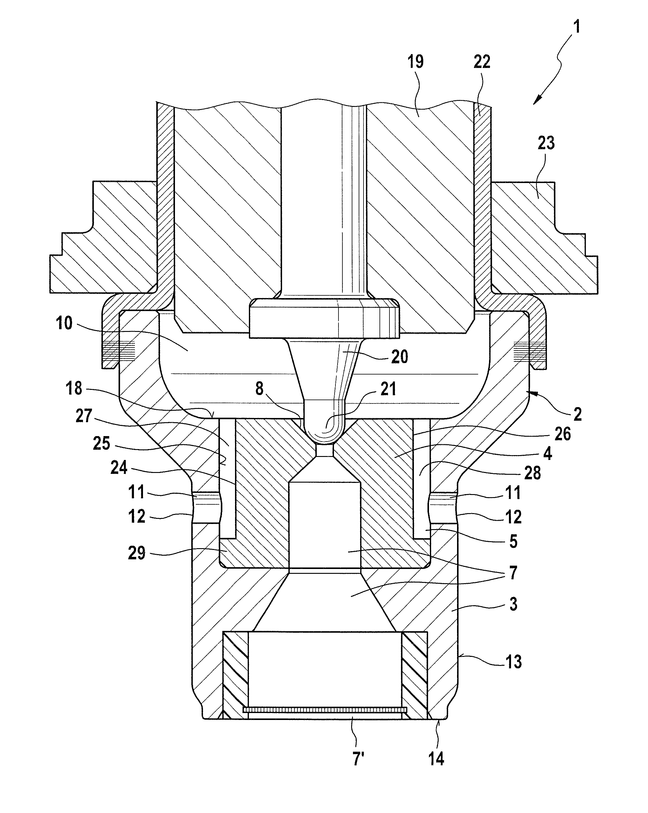
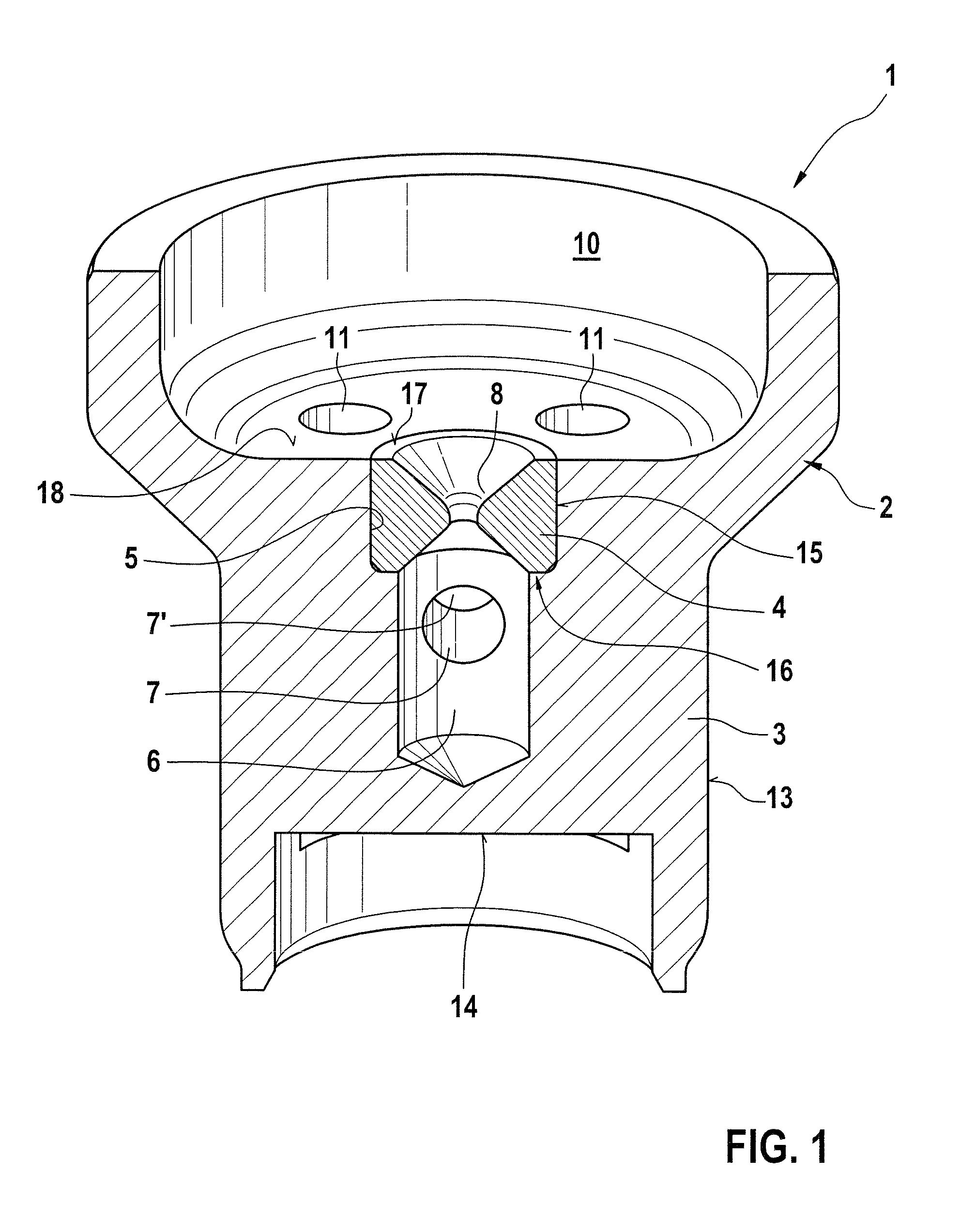
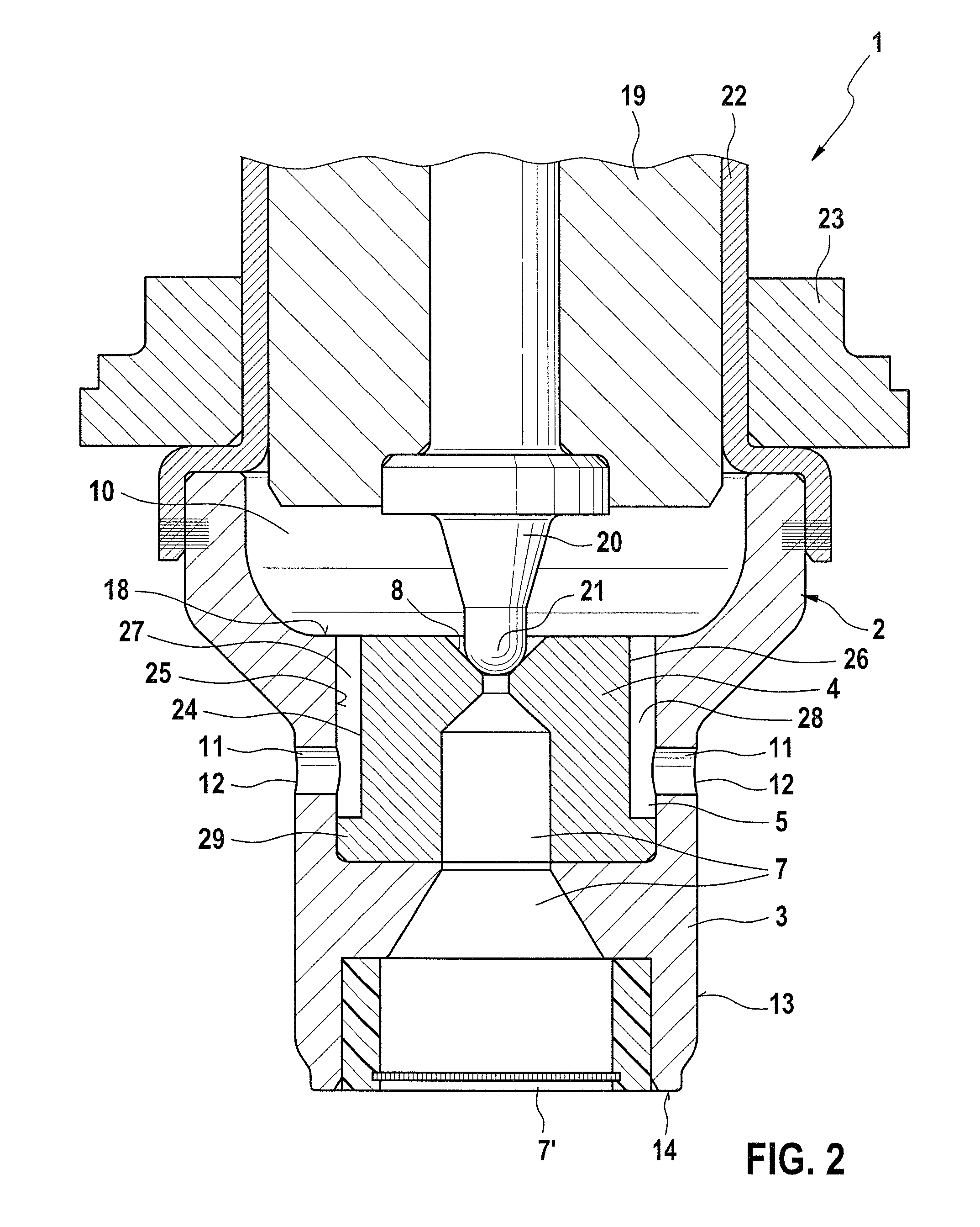
[0021]FIG. 1 shows a cross section of a region of a magnet valve 1, in which only one valve body 2 is shown. The valve body 2 comprises a base body 3 and an insert part 4, which insert part is disposed in a receptacle region 5 of the base body 3 or of the valve body 2. A riser conduit 6 is embodied in the valve body 2 and is in fluidic communication via an inlet conduit 7 with at least one inlet port 7′. Via the inlet port 7′, the magnet valve 1 can be supplied with a fluid. The fluid supplied through the inlet port 7′ flows through a valve seat 8, which is embodied by the insert part 4, when the insert part is opened by a sealing element, not shown here. On the side of the valve seat 8 remote from the riser conduit 6, a fluid chamber 10 is provided, which is embodied in at least some regions by the valve body 2. Moreover, at least one outlet conduit 11, which discharges into the fluid chamber 10, is provided in the valve body 2. There is a permanent fluidic communication between th...
PUM
 Abstract
Description
Claims
Application Information