Multi-component wiper arm

a technology of wiper arms and components, applied in vehicle maintenance, vehicle cleaning, cleaning equipment, etc., can solve the problems of high cost, time-consuming production and assembly of wiper arms, and the risk of individual components being separated from one another, and achieves the effect of simple and low-cost production

Inactive Publication Date: 2014-06-10
ROBERT BOSCH GMBH
View PDF5 Cites 28 Cited by
  • Summary
  • Abstract
  • Description
  • Claims
  • Application Information

AI Technical Summary

Benefits of technology

[0004]It is therefore an object of the present invention to provide a wiper arm which can be produced easily and quickly and at the same time has great reliability and stability during operation.
[0009]A particularly simple and low-cost variant of the process according to the invention envisages using the same material component, in particular the same thermoplastic material, for the production of the upper arm portion and the wiper blade holder, the thermoplastic material of the upper arm portion and the wiper blade holder being made to match the thermoplastic material of the lower arm portion in such a way that the two different types of plastic do not bond to each other.

Problems solved by technology

However, this kind of production and assembly of the wiper arm is very time-intensive and involves high costs because of the non-productive times caused by the closer necessary injection-molding machines and the additional assembly.
The necessity for the individual components to be clipped to one another during the assembly causes the risk of unwanted detachment of the individual components from one another during the operation of the window wiper arm.

Method used


Image

  • Multi-component wiper arm
  • Multi-component wiper arm
  • Multi-component wiper arm

Examples


Embodiment Construction

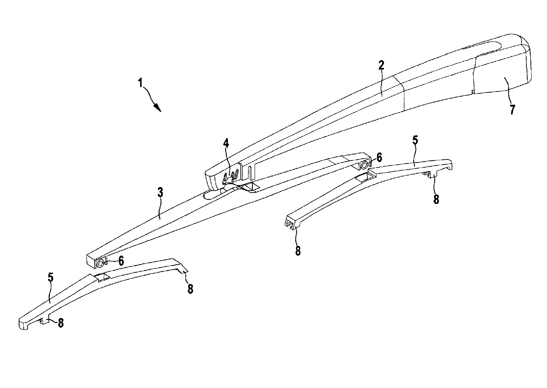
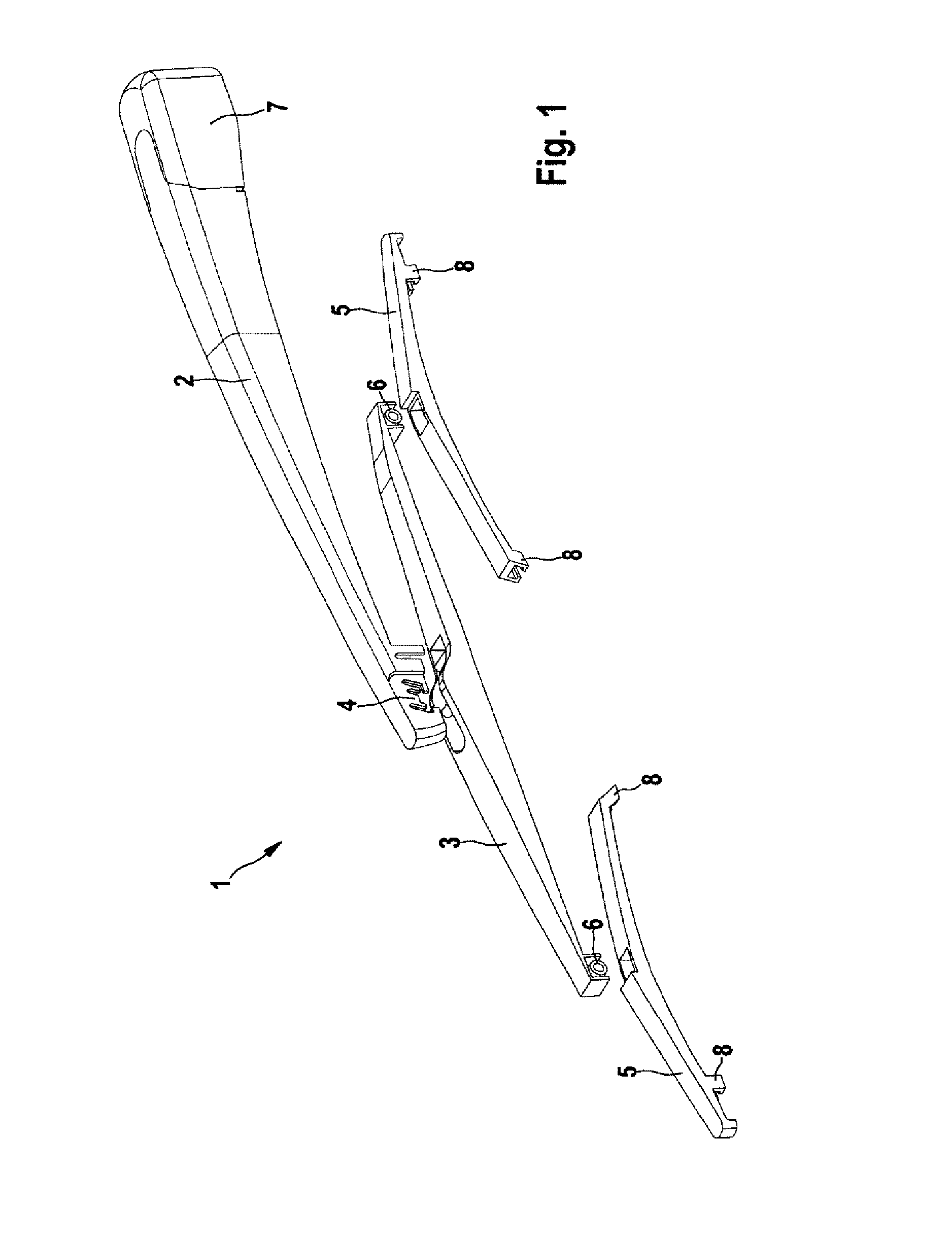
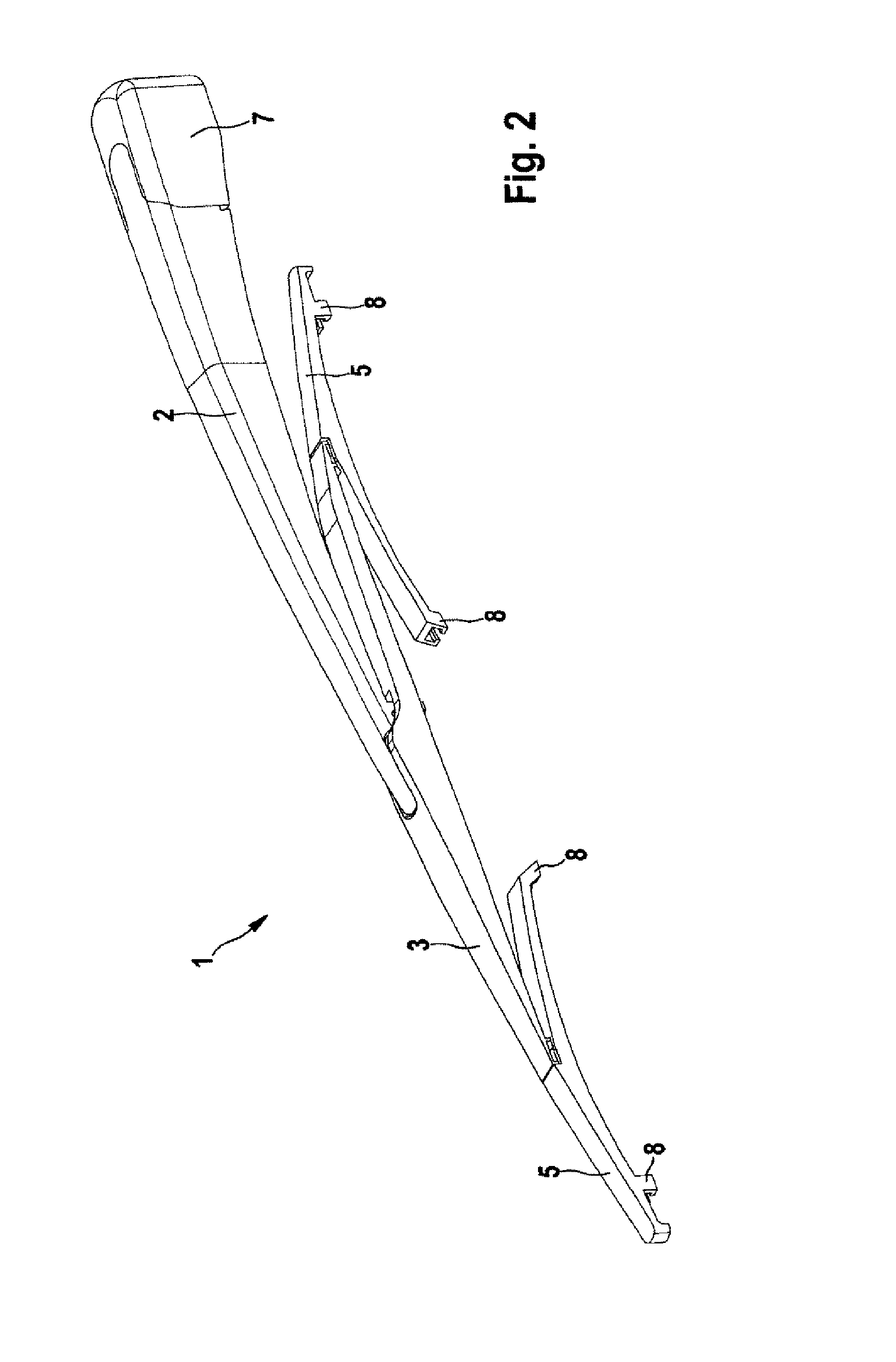
[0026]FIG. 1 shows an exploded drawing of a wiper arm 1 according to the invention, which has an upper arm portion 2 and a lower arm portion 3, which are movably connected to each other by way of a pivot pin 4. On the lower arm portion 3, two wiper blade holders 5 are movably connected to the lower arm portion 3 respectively by way of a pivot pin 6. At its free end, the upper arm portion 2 has a mount 7, in order to be able to fix the wiper arm 1 detachably to a wiper drive (not represented) of the window wiper device (likewise not represented). Before the wiper arm 1 is then fitted on the window wiper device, all that is then necessary is to insert wiper blades into the clips 8 provided for this purpose on the wiper blade holder 5.

[0027]The production of a ready-assembled two-component wiper arm 1 can be produced according to the invention completely in one injection-molding cycle. It is consequently possible to dispense with production of individual components in different injecti...


PUM

PropertyMeasurementUnit
shrinkage propertiesaaaaaaaaaa
stabilityaaaaaaaaaa
shrinkage behaviorsaaaaaaaaaa

Abstract

The present invention relates to a process for producing a wiper arm for a window wiper device for a motor vehicle, with an upper arm portion, on which a mount is provided, in order to fix the wiper arm detachably to a wiper drive of the window wiper device, and a lower arm portion, which is pivotably connected to the upper arm portion, as well as at least one wiper blade holder which is pivotably connected to the lower arm portion, characterized by producing the wiper arm in a multi-component injection-molding process in which, in a first process step, the upper arm portion is injection-molded along with at least one first pivot pin formed on it by means of a first material component in a partial portion of a cavity, in a second process step the lower arm portion, pivotably connected to the upper arm portion, is injection-molded along with at least one second pivot pin formed on it by means of a second material component in a second partial portion of the cavity by encapsulation of the first pivot pin, and in a further process step at least one wiper blade holder is injection-molded by means of a third material component in a further partial portion of the cavity by encapsulation of the second pivot pin.

Description

BACKGROUND OF THE INVENTION[0001]The present invention relates to a process for producing a multi-component wiper arm for a window wiper device for a motor vehicle, with an upper arm portion, on which a mount is provided, in order to fix the wiper arm detachably to a wiper drive of the window wiper device, and a lower arm portion, which is pivotably connected to the upper arm portion, as well as at least one wiper blade holder, which is pivotably connected to the lower arm portion. Furthermore, the present invention relates to a wiper arm produced by means of a multi-component assembly injection-molding process.[0002]It is already known to produce the connection of a wiper arm to its various components separately by the injection-molding process and connect them to one another in a further working step. In the prior art, the various subassemblies of the wiper arm are normally first produced in different injection molds on separate injection-molding machines. Subsequently, the indivi...

Claims


Application Information

Patent Timeline
Patent Type & Authority Patents(United States)
IPC IPC(8): B60S1/40
CPCB60S1/4064B60S2001/3898B60S1/34B60S1/3801
Inventor KRUSE, MICHAELGEISE, STEPHAN
Owner ROBERT BOSCH GMBH
Why Eureka
Try Eureka