Display device

a display device and display technology, applied in the field of display devices, can solve problems such as persistent image (burning) and achieve the effects of reducing image persistence (burning) of display devices, and low cos

Active Publication Date: 2014-07-01
MAXELL HLDG LTD
View PDF8 Cites 2 Cited by
  • Summary
  • Abstract
  • Description
  • Claims
  • Application Information

AI Technical Summary

Benefits of technology

[0011]By carrying out the display of the dashes so as to move, at fixed time intervals or arbitrary time intervals, the dash display areas of the aforementioned auxiliary lines on the trajectory of the figure described by the aforementioned auxiliary lines, the system is devised to display the auxiliary lines so that the display of an identical pixel of the display device is reduced.
[0022]Moreover, the system is devised to: comprise a light source provided with a light adjusting means adjusting the quantity of light of a display image; a fan carrying out the cooling of a heat generation block; and a fan drive circuit driving the aforementioned fan; and, during auxiliary line image display, to increase or decrease the quantity of light of the display image, with respect to an auxiliary line image, and, by associating it with a change in the aforementioned quantity of light, control the rotation rate of the aforementioned fan.
[0026]According to the present invention, it is possible to furnish an image display device that, more than conventionally, reduces the image persistence (burn-in) of display devices and makes possible the display of auxiliary lines in an identical position. In addition, it is possible, more than conventionally, to reduce image persistence (burn-in) of display devices without adding special circuits and make an implementation thereof at low cost.

Problems solved by technology

As for the display of auxiliary lines targeting assistance in recording, there is a need to hold the display position for a long time, but as far as liquid crystal devices used in projection type image display devices are concerned, there is, in the case of displaying a luminance or a color that is different from the background region for a long time in the same position, the problem that a persistent image (burn-in) occurs, since a DC voltage component remains.

Method used


Image

  • Display device
  • Display device
  • Display device

Examples


first embodiment

1. The First Embodiment

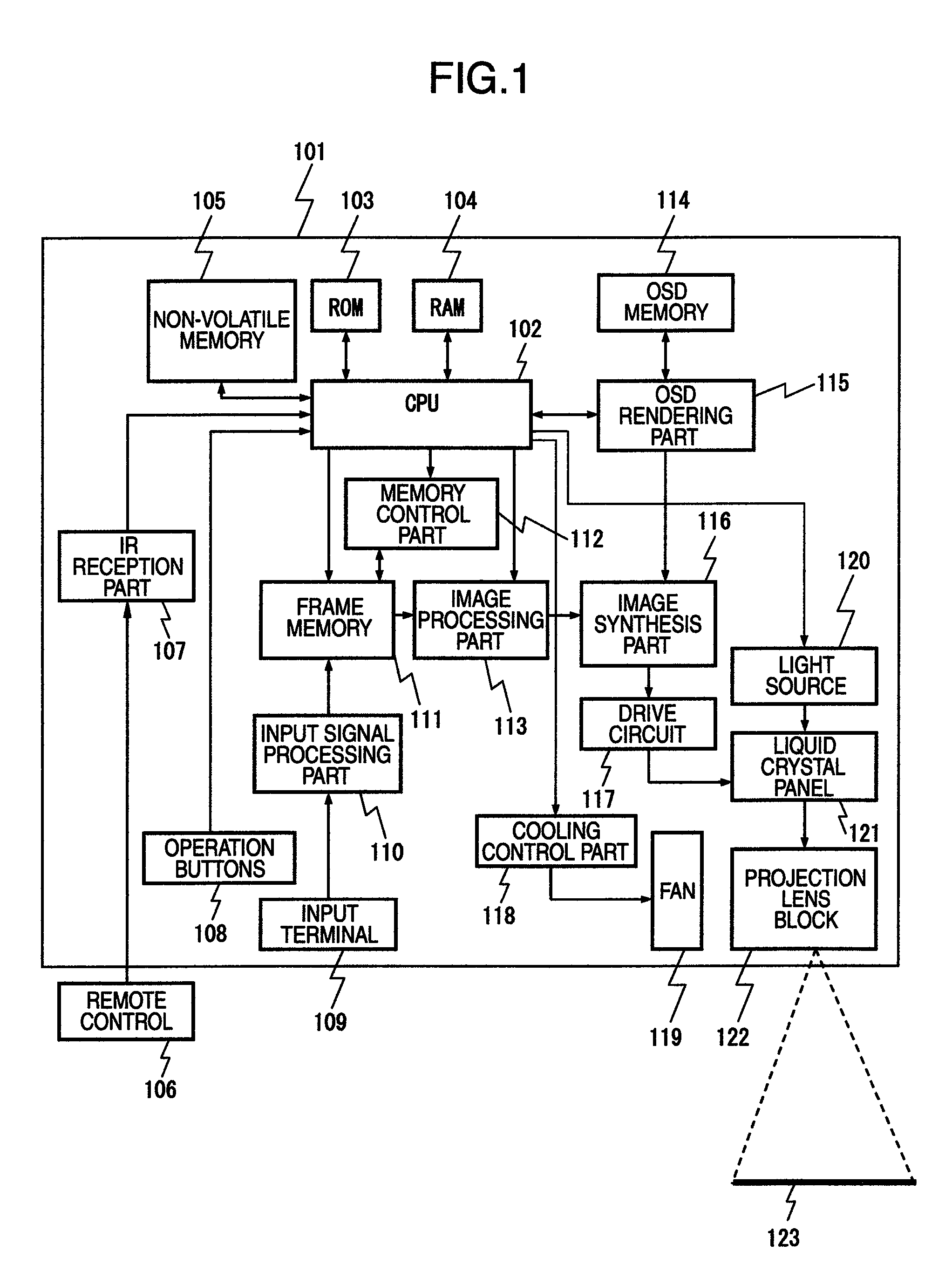
[0039]FIG. 1 is a block diagram of a projection type image display device exhibiting Embodiment 1. In FIG. 1, ref. 101 is a projection type image display device, 109 is an input terminal into which a (not illustrated) video signal is input, 110 is an input signal processing part carrying out prescribed signal processing with respect to video signals input from input terminal 109, 111 is a frame memory temporarily storing video signals output from input signal processing part 110, 112 is a memory control part controlling reads to and from the frame memory, 113 is an image processing part carrying out scaling such as image enlargement and reduction as well as geometric distortion correction with respect to video signals read from the frame memory, 102 is a Central Processing Unit (below abbreviated as “CPU”) carrying out arithmetic control of the whole projection type image display device, 103 is a Read Only Memory (including a Flash ROM and below abbreviated as...

second embodiment

2. The Second Embodiment

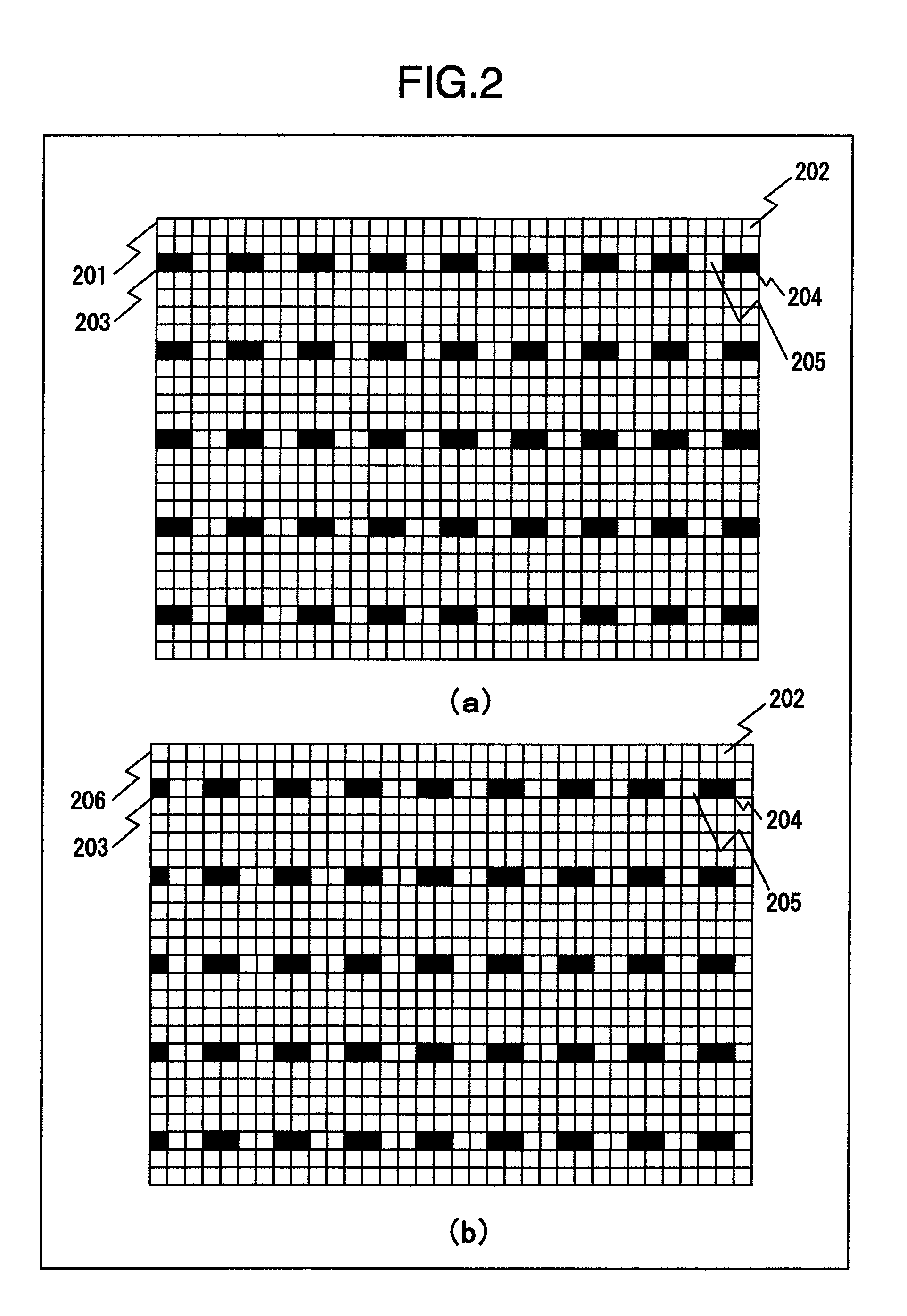
[0053]FIG. 4 are diagrams explaining a display method for registered auxiliary line image display associated with the present invention. In FIG. 4B, 401 is an auxiliary line image in which the display color of pixel 204, whose luminance or color differs from the background color being a constituent element of auxiliary line 203 of auxiliary line image 201, is taken to have the same luminance or color as that of the background color and pixel 205 is taken to have a display color whose luminance or color differs from the background color of pixel 204.

[0054]Next, there will be a mention regarding the operation.

[0055]In ROM 103, auxiliary line image 201 and auxiliary line image 401 are pre-stored. CPU 102 carries out processing corresponding, respectively to a (not illustrated) button out of operation buttons 108 or a remote IR signal received via IR reception part 107. In case an operation button associating an auxiliary line display is input, CPU 102, via memor...

third embodiment

3. The Third Embodiment

[0058]FIGS. 5-(a) and (b) are explanatory diagrams in which the intervals in an auxiliary line image are adjusted. Ref. 502 indicates an auxiliary line interval. Ref. 501 is an auxiliary line image in which the auxiliary line interval is adjusted and 503 indicates the auxiliary line interval of auxiliary line image 501.

[0059]FIGS. 6-(a) and (b) are explanatory diagram in which the background color of the auxiliary line image is adjusted. Ref. 601 is an auxiliary line image in which the background color of auxiliary line image 201 has been adjusted, 602 shows one background color pixel in which the display luminance or color has been adjusted, and 603 shows a pixel whose luminance or color, in conjunction with an adjustment of the luminance or color of the background pixels, is the same as the background color and which is a constituent element of auxiliary line 203 whose display luminance or color is nearly the same as the background color.

[0060]Embodiment 3 w...


PUM


Abstract

In a display device provided with a frame memory developing an auxiliary line image as a display image and a means of reading out and displaying the image data developed in the aforementioned frame memory, the aforementioned auxiliary line image is constituted by background pixels and dashed auxiliary lines constituted by pixels which have luminance or color that is different from that of the background color and pixels with have nearly identical luminance or color to that of the background color; and by carrying out the display of the dashes so as to move, at fixed time intervals or arbitrary time intervals, the dash display areas of the aforementioned auxiliary lines on the trajectory of the figure described by the aforementioned auxiliary lines, the system is devised to display the auxiliary lines while controlling that an identical pixel of the display device is not displayed continually.

Description

BACKGROUND OF THE INVENTION[0001]1. Field of the Invention[0002]The present invention is one that pertains to technology providing a display device.[0003]2. Description of the Related Art[0004]In recent years, along with the spread of Personal Computers as well as IT (Information Technology) infrastructure development, projection type image display devices, starting with projectors, have spread with high speed in various settings such as at conference presentations and for lectures at education sites.[0005]Moreover, accompanying the spread, the trend toward higher luminance is advancing together with a reduction in price. As a result hereof, since it has not been possible in the past to obtain sufficient brightness for display images of projection type image display devices, it has been necessary to project on a dedicated screen to make the projection. Under present conditions, since it is possible to procure projection type image display devices comparatively inexpensively and with...

Claims


Application Information

Patent Timeline
Patent Type & Authority Patents(United States)
IPC IPC(8): G09G5/00
CPCG09G5/10G03B21/00G03B21/14H04N9/3185G03B21/006
Inventor ONODERA, SHINJIATSUTA, KOICHIMUKAI, YUSUKEIWAHARA, KENICHI
Owner MAXELL HLDG LTD
Why Eureka
Try Eureka