Display device
- Summary
- Abstract
- Description
- Claims
- Application Information
AI Technical Summary
Benefits of technology
Problems solved by technology
Method used
Image
Examples
first embodiment
1. The First Embodiment
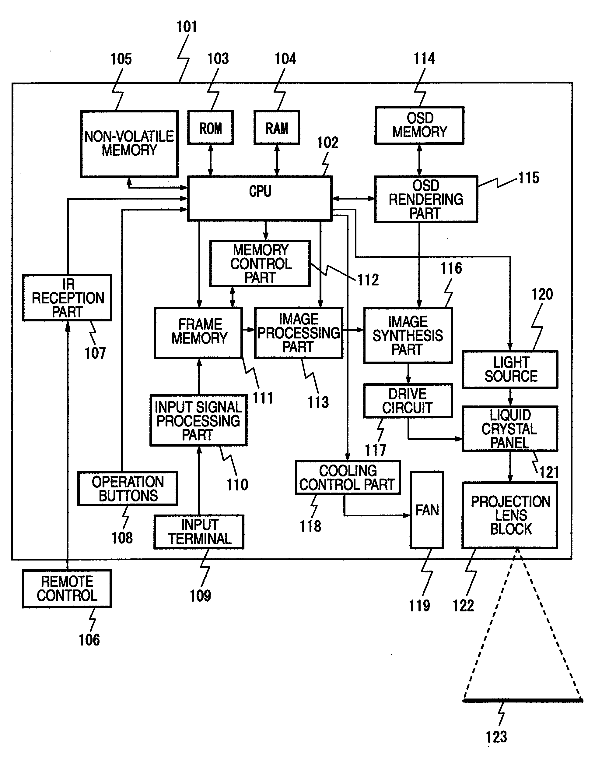
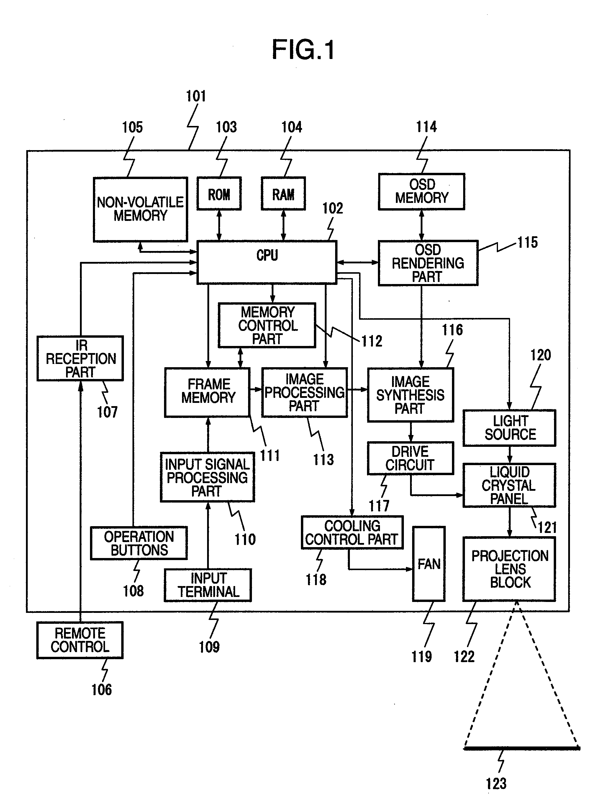
[0039]FIG. 1 is a block diagram of a projection type image display device exhibiting Embodiment 1. In FIG. 1, ref. 101 is a projection type image display device, 109 is an input terminal into which a (not illustrated) video signal is input, 110 is an input signal processing part carrying out prescribed signal processing with respect to video signals input from input terminal 109, 111 is a frame memory temporarily storing video signals output from input signal processing part 110, 112 is a memory control part controlling reads to and from the frame memory, 113 is an image processing part carrying out scaling such as image enlargement and reduction as well as geometric distortion correction with respect to video signals read from the frame memory, 102 is a Central Processing Unit (below abbreviated as “CPU”) carrying out arithmetic control of the whole projection type image display device, 103 is a Read Only Memory (including a Flash ROM and below abbreviated as...
second embodiment
2. The Second Embodiment
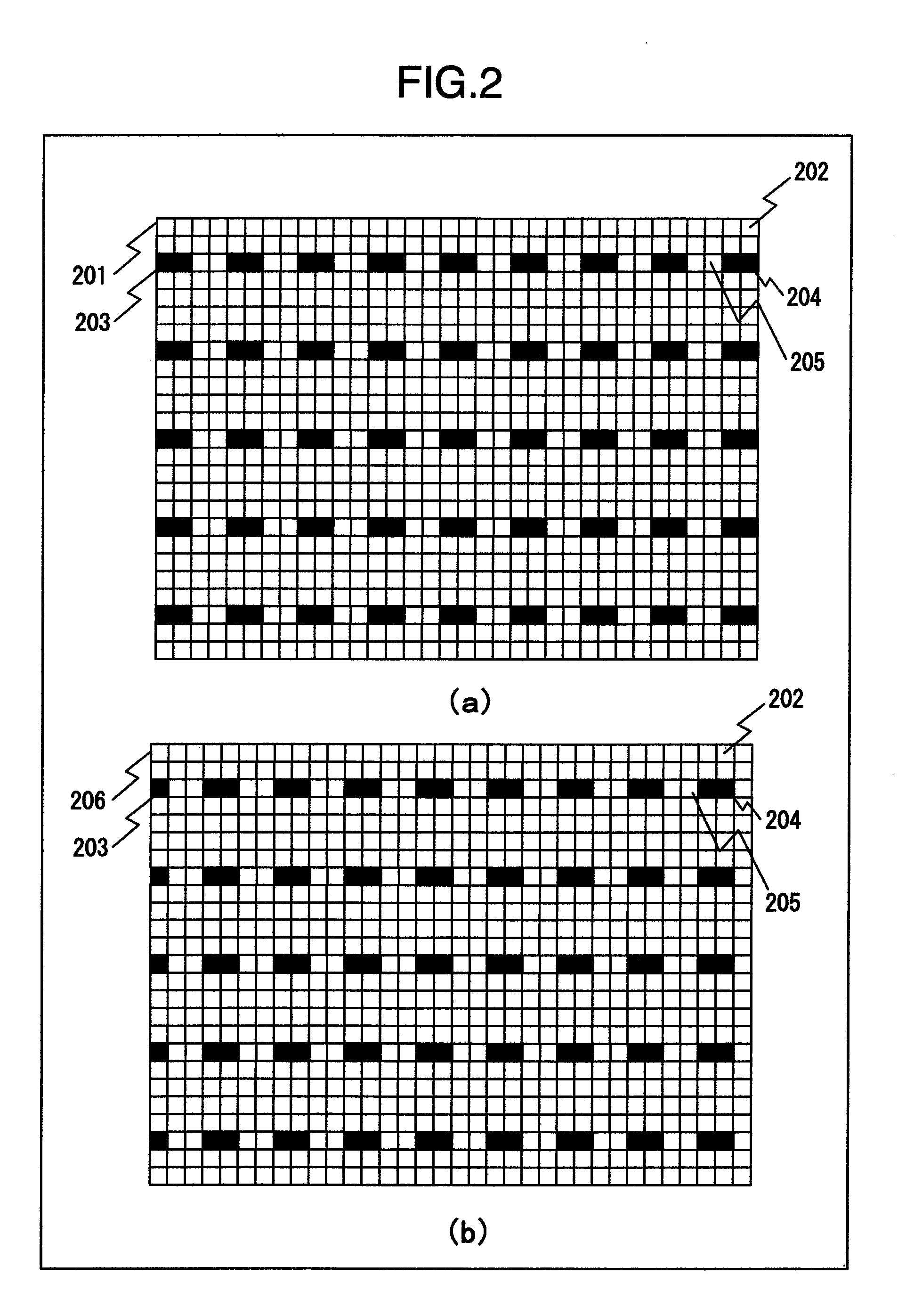
[0053]FIG. 4 are diagrams explaining a display method for registered auxiliary line image display associated with the present invention. In FIG. 4B, 401 is an auxiliary line image in which the display color of pixel 204, whose luminance or color differs from the background color being a constituent element of auxiliary line 203 of auxiliary line image 201, is taken to have the same luminance or color as that of the background color and pixel 205 is taken to have a display color whose luminance or color differs from the background color of pixel 204.
[0054]Next, there will be a mention regarding the operation.
[0055]In ROM 103, auxiliary line image 201 and auxiliary line image 401 are pre-stored. CPU 102 carries out processing corresponding, respectively to a (not illustrated) button out of operation buttons 108 or a remote IR signal received via IR reception part 107. In case an operation button associating an auxiliary line display is input, CPU 102, via memor...
third embodiment
3. The Third Embodiment
[0058]FIGS. 5-(a) and (b) are explanatory diagrams in which the intervals in an auxiliary line image are adjusted. Ref. 502 indicates an auxiliary line interval. Ref. 501 is an auxiliary line image in which the auxiliary line interval is adjusted and 503 indicates the auxiliary line interval of auxiliary line image 501.
[0059]FIGS. 6-(a) and (b) are explanatory diagram in which the background color of the auxiliary line image is adjusted. Ref. 601 is an auxiliary line image in which the background color of auxiliary line image 201 has been adjusted, 602 shows one background color pixel in which the display luminance or color has been adjusted, and 603 shows a pixel whose luminance or color, in conjunction with an adjustment of the luminance or color of the background pixels, is the same as the background color and which is a constituent element of auxiliary line 203 whose display luminance or color is nearly the same as the background color.
[0060]Embodiment 3 w...
PUM
 Abstract
Description
Claims
Application Information
 - R&D
- Intellectual Property
- Life Sciences
- Materials
- Tech Scout
- Unparalleled Data Quality
- Higher Quality Content
- 60% Fewer Hallucinations
Browse by: Latest US Patents, China's latest patents, Technical Efficacy Thesaurus, Application Domain, Technology Topic, Popular Technical Reports.
© 2025 PatSnap. All rights reserved.Legal|Privacy policy|Modern Slavery Act Transparency Statement|Sitemap|About US| Contact US: help@patsnap.com


