Liquid crystal composition and liquid crystal display device

a liquid crystal display and composition technology, applied in the direction of liquid crystal compositions, chemistry apparatuses and processes, etc., can solve the problems of long service life of devices, and achieve the effects of increasing dielectric anisotropy, increasing optical anisotropy, and reducing viscosity

Inactive Publication Date: 2015-10-08
JNC CORP +1
View PDF12 Cites 19 Cited by
  • Summary
  • Abstract
  • Description
  • Claims
  • Application Information

AI Technical Summary

Benefits of technology

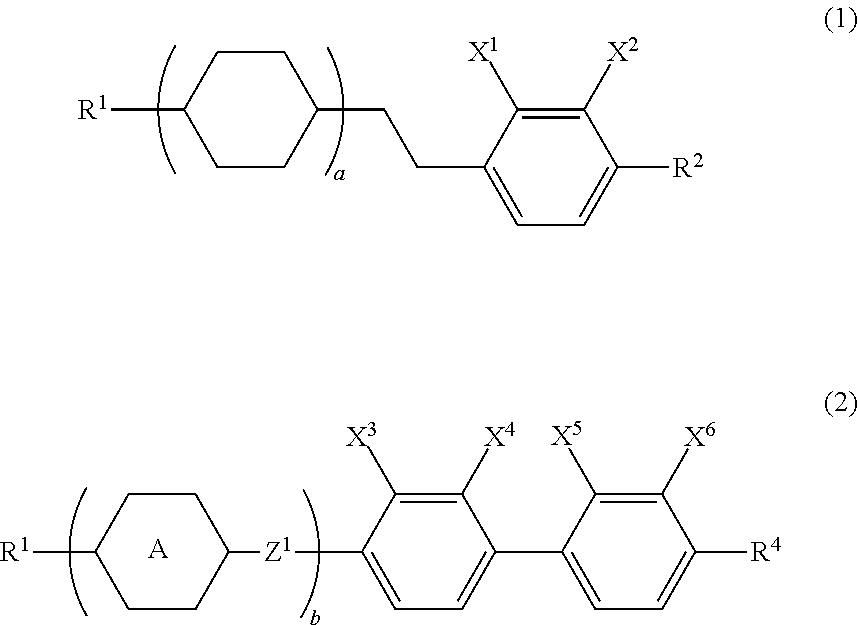
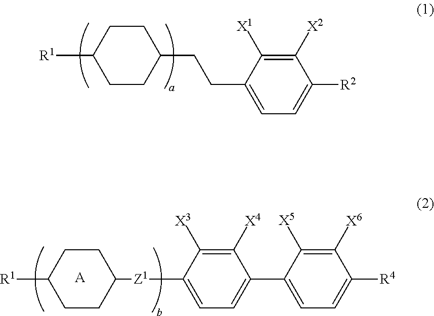
[0048]Upon mixing the component compounds in the composition, the main effects of the component compounds on the characteristics of the composition are as described below. Compound (1) increases the dielectric anisotropy. Compound (2) increases the optical anisotropy. Compound (3) decreases the viscosity and increases the maximum temperature. Compound (4) increases the dielectric anisotropy and decreases the minimum temperature. Compound (5) is polymerized to give a polymer, and the polymer shortens the response time of the device and reduces image persistence.
[0049]Third, the combination of components in the composition, preferred proportions of the component compounds and the bases thereof are described. A preferred combination of the components in the composition is a combination of the 1st component and the 2nd component, a combination of the 1st component, the 2nd component and the 3rd component, a combination of the 1st component, the 2nd component and the 4th component, a combination of the 1st component, the 2nd component and the additive component, a combination of the 1st component, the 2nd component, the 3rd component and the 4th component, a combination of the 1st component, the 2nd component, the 3rd component and the additive component, a combination of the 1st component, the 2nd component, the 4th component and the additive component, or a combination of the 1st component, the 2nd component, the 3rd component, the 4th component and the additive component. A further preferred combination is the combination of the 1st component, the 2nd component and the 3rd component, the combination of the 1st component, the 2nd component, the 3rd component and the 4th component, the combination of the 1st component, the 2nd component, the 3rd component and the additive component, or the combination of the 1st, the 2nd, the 3rd the 4th and the additive components.
[0050]A preferred proportion of the first component is about 5 wt % or more for increasing Δ∈, and about 50 wt % or less for decreasing the minimum temperature. A further preferred proportion is in the range of about 5 wt % to about 40 wt %. A particularly preferred proportion is in the range of about 5 wt % to about 30 wt %.
[0051]A preferred proportion of the second component is about 5 wt % or more for increasing Δn, and about 50 wt % or less for decreasing the minimum temperature. A further preferred proportion is in the range of about 5 wt % to about 40 wt %. A particularly preferred proportion is in the range of about 5 wt % to about 35 wt %.
[0052]A preferred proportion of the third component is about 10 wt % or more for increasing the maximum temperature or decreasing the viscosity, and about 90 wt % or less for increasing the dielectric anisotropy. A further preferred proportion is in the range of about 20 wt % to about 70 wt %. A particularly preferred proportion is in the range of about 25 wt % to about 60 wt %.
[0053]A preferred proportion of the fourth component is about 5 wt % or more for increasing Δ∈, and about 70 wt % or less for decreasing the minimum temperature. A further preferred proportion is in the range of about 5 wt % to about 50 wt %. A particularly preferred proportion is in the range of about 5 wt % to about 40 wt %.

Problems solved by technology

In cases where the stability is high, the device has a long service life.

Method used


Image

  • Liquid crystal composition and liquid crystal display device
  • Liquid crystal composition and liquid crystal display device
  • Liquid crystal composition and liquid crystal display device

Examples


examples

[0094]The invention will be described in more details by way of Examples, but is not restricted thereto. For example, the invention may include a mixture of the composition of Example 1 and that of Example 2, or a mixture in which at least two compositions in Examples were mixed. A compound synthesized was identified by a method such as an NMR analysis. Characteristics of the compound and the composition were measured by methods described below.

[0095]NMR analysis: DRX-500 made by Bruker BioSpin Corporation was used for the measurement. In a 1H-NMR measurement, a sample was dissolved in a deuterated solvent such as CDCl3, and measurement was carried out under conditions of room temperature, 500 MHz and 16 times of accumulation. Tetramethylsilane was used as an internal standard. In 19F-NMR measurement, measurement was carried out under conditions of 24 times of accumulation using CFCl3 as an internal standard. In explaining an NMR spectrum, s, d, t, q, quin, sex and m stand for a sin...

example 1

[0119]

V-HH2B (2F, 3F)-O2(1-2)10%5-B (F) BB-2(2-4) 6%3-HBB-2(2-7) 3%3-HH-V(3-1)24%5-HH-V(3-1) 3%3-HH-V1(3-1) 8%3-HH-VFF(3-1) 4%V2-HHB-1(3-4)10%3-H1OB (2F, 3F)-O2(4-2) 9%V-HHB (2F, 3F)-O1(4-3) 8%V-HHB (2F, 3F)-O2(4-3) 7%3-HH1OB (2F, 3F)-O2(4-4) 5%3-H1OCro (7F, 8F)-5(4-9) 3%

NI=89.9° C.; Tc<−20° C.; Δn=0.095; Δ∈=−2.8; Vth=2.55 V; η=18.2 mPa·s.

example 2

[0120]

V-HH2B (2F, 3F)-O2(1-2)11%1-BB-5(2-1) 7%3-BB (2F, 3F)-O4(2-2) 3%2O-B (2F, 3F) B (2F, 3F)-O6(2-3) 3%2-BB (2F, 3F) B-3(2-6) 6%3-HH-V(3-1)28%3-HH-V1(3-1) 9%V-HHB (2F, 3F)-O1(4-3) 5%V-HHB (2F, 3F)-O2(4-3)11%3-HH1OB (2F, 3F)-O2(4-4)10%V2-BB (2F, 3F)-O2(-) 7%

NI=76.9° C.; Tc<−20° C.; Δn=0.107; Δ∈=−3.1; Vth=2.38 V; η=16.7 mPa·s; VHR-1=99.1%; VHR-2=98.2%.


PUM

PropertyMeasurementUnit
temperatureaaaaaaaaaa
response timeaaaaaaaaaa

Abstract

A liquid crystal composition and an AM LCD device including the same are described. The liquid crystal composition has a negative dielectric anisotropy and contains a specific compound having a large negative dielectric anisotropy as a first component and a compound having a large optical anisotropy as a second component, and may further contain a specific compound having a high maximum temperature or a small viscosity as a third component, a specific compound having a large negative dielectric anisotropy as a fourth component, and/or a specific compound having a polymerizable group as an additive component.

Description

CROSS-REFERENCE TO RELATED APPLICATION[0001]This application claims the priority benefits of Japanese Patent Application serial no. 2014-076370, filed on Apr. 2, 2014, and Japanese Patent Application serial no. 2014-202813, filed on Oct. 1, 2014. The entirety of each of the above-mentioned patent applications is hereby incorporated by reference herein and made a part of this specification.TECHNICAL FIELD[0002]The invention relates to a liquid crystal composition, a liquid crystal display (LCD) device including the composition and so forth. In particular, the invention relates to a liquid crystal composition having a negative dielectric anisotropy, and an LCD device that includes the composition and has a mode such as an IPS mode, a VA mode, an FFS mode or an FPA mode, and also relates to an LCD device having a polymer sustained alignment (PSA) mode.BACKGROUND ART[0003]For LCD devices, a classification based on the operating mode of liquid crystal molecules includes a phase change (P...

Claims


Application Information

Patent Timeline
Patent Type & Authority Applications(United States)
IPC IPC(8): C09K19/34C09K19/54C09K19/30
CPCC09K2019/3422C09K2019/548C09K19/3402C09K2019/3425C09K19/3001C09K19/542C09K19/3066C09K19/3028C09K19/3068C09K2019/0448C09K2019/122C09K2019/123C09K2019/3016C09K2019/3027C09K2019/3036C09K2019/3037C09K2019/3078
Inventor FURUSATO, YOSHIMASASAITO, MASAYUKI
Owner JNC CORP
Why Eureka
Try Eureka