Motorized syringe for use with two types of dental anesthetic solution-containing cartridges

a technology of motorized syringes and cartridges, which is applied in the field of motorized syringes, can solve the problems of undesirable inventions disclosed in patent reference 1

Active Publication Date: 2014-09-23
GC SHOWAYAKUHIN CORP
View PDF6 Cites 0 Cited by
  • Summary
  • Abstract
  • Description
  • Claims
  • Application Information

AI Technical Summary

Benefits of technology

[0024]According to the invention, the cartridge holder is configured to be used in common for both a 1.0 ml cartridge and a 1.8 ml cartridge, the push rod has a 1.0 ml cartridge-setting position and a 1.8 ml cartridge-setting position drawn back from the 1.0 ml cartridge-setting position, so that the movement of the push rod can end at its common terminal position for 1.0 ml and 1.8 ml cartridges, and due to the fact that the syringe comprises the bottomed sleeve for receiving the rear end portion of the push rod therein when the push rod is pushed back from the common terminal position, the sleeve being pushed rearward with the rear end face of the push rod when the push rod is pushed back to the 1.8 ml cartridge-setting position, and the return spring for moving forward the sleeve together with the push rod upon the forward movement of the push rod, the plunger rubber plug in the 1.8 ml cartridge can be pushed by the push rod the distance required to push the plunger rubber plug in the 1.0 ml cartridge. Thus, the invention can provide a motorized syringe of compact configuration.

Problems solved by technology

However, the invention disclosed in patent reference 1 is undesirable because it does not make a configuration of the motorized syringe compact.

Method used


Image

  • Motorized syringe for use with two types of dental anesthetic solution-containing cartridges
  • Motorized syringe for use with two types of dental anesthetic solution-containing cartridges
  • Motorized syringe for use with two types of dental anesthetic solution-containing cartridges

Examples


Embodiment Construction

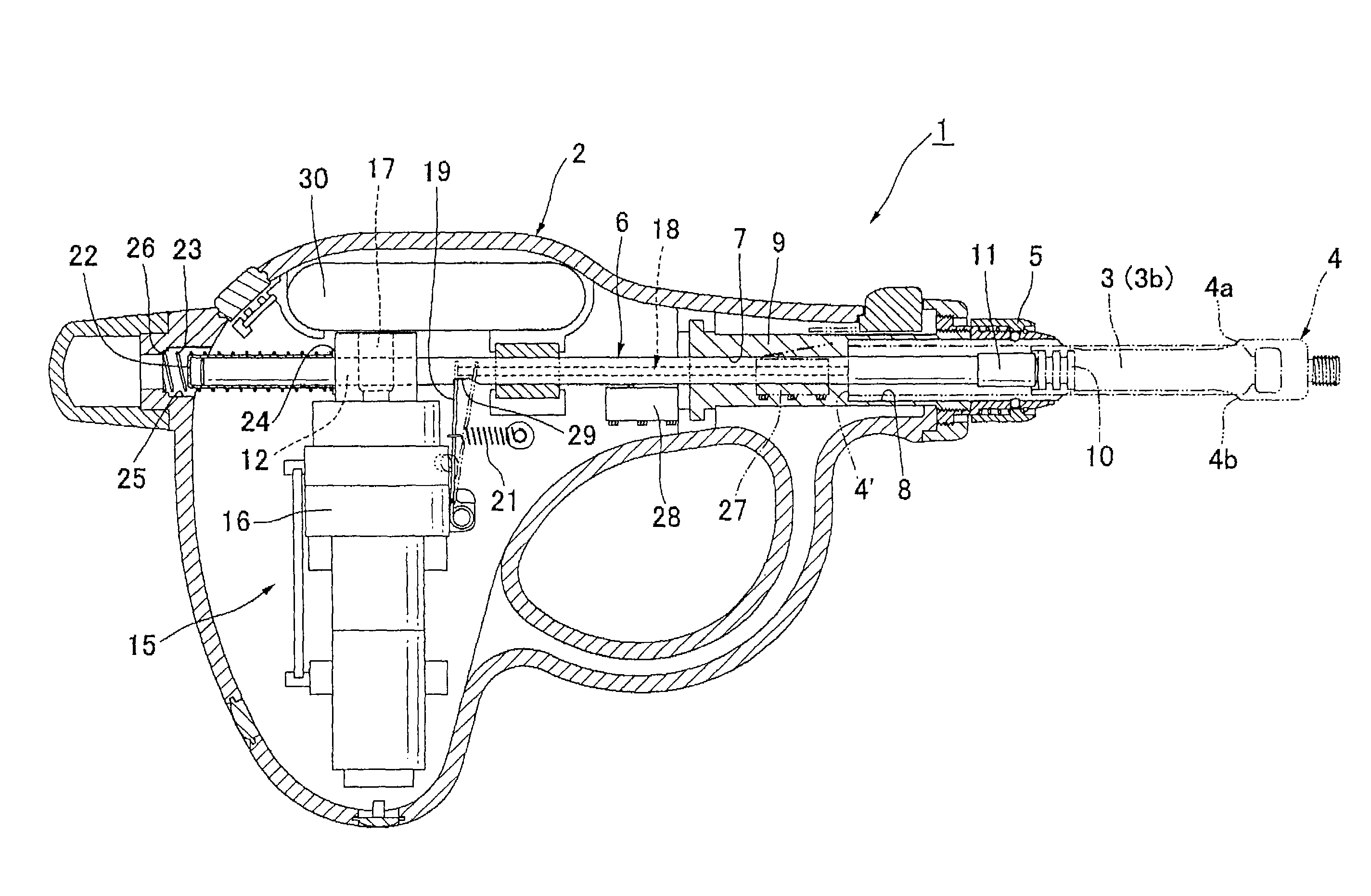
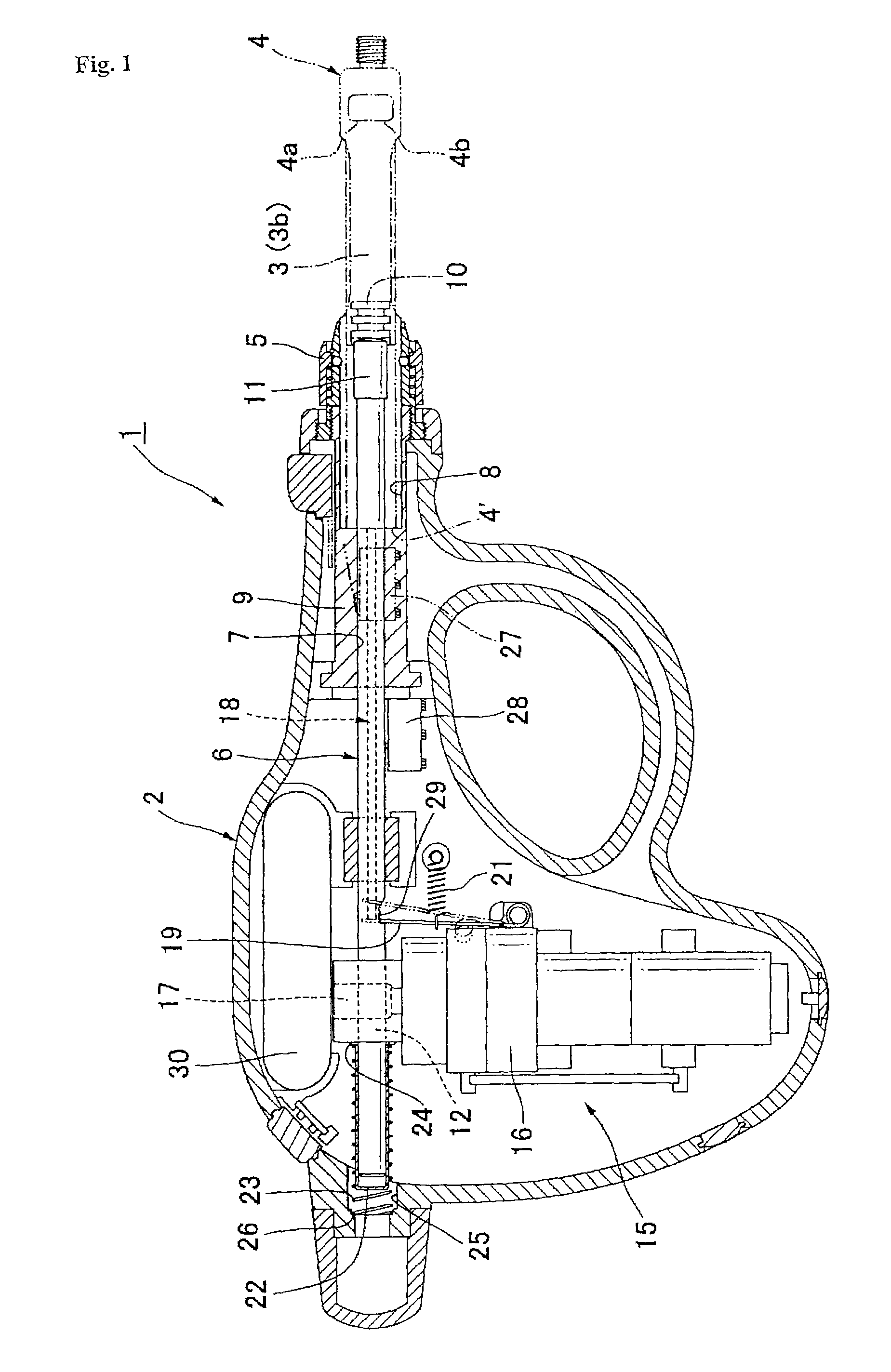
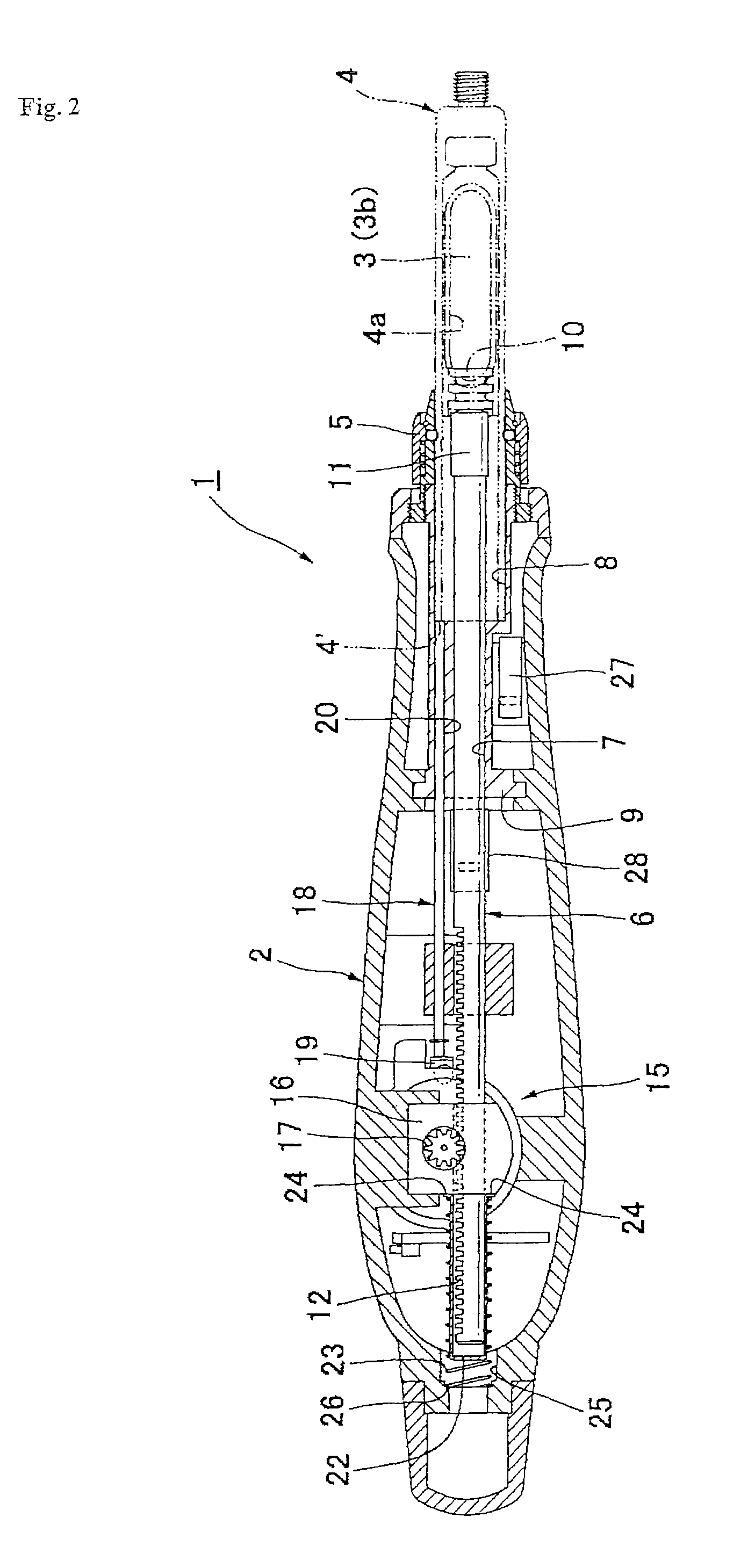
[0016]Referring to FIG. 1 of the drawings, a motorized syringe 1 according to the invention is shown and comprises a syringe body 2 formed from plastics, and a coupling 5 for detachably connecting to the syringe at its forward end a metallic cartridge holder 4 having an anesthetic solution-filled cartridge 3 loaded therein. The coupling 5 is threadedly affixed to a metallic support member 9 secured to the syringe body 2 having a through-hole 7 through which a metallic round push rod 6 is passed, the support member 9 also having a socket 8 into which the cartridge holder 4 is inserted when it is connected to the syringe body by the coupling 5.

[0017]Cartridge holder 4 has windows 4a, 4b formed therein on the opposite sides, the windows being convenient to view the cartridge loaded in the cartridge holder from the exterior. The cartridge holder 4 can be used commonly for both of the cartridges 3b and 3a containing anesthetic solution of 1.0 ml and 1.8 ml, respectively, and is sized suc...


PUM


Abstract

A motorized syringe for use with two types of dental anesthetic solution-filled cartridges, having a plunger plug in the 1.8 ml cartridge pushed by a push rod by a length required to push a plunger plug in the 1.0 ml cartridge. The syringe includes a cartridge holder for use with 1.0 ml and 1.8 ml cartridges, the push rod having a 1.0 ml position and a 1.8 ml position drawn back from the 1.0 ml position so that push rod movement can end at a common terminal position for both, a sleeve adapted to receive the push rod rear end when pushed back from the common terminal position, and to be not interfered with by the push rod's rear end when it is in the 1.0 ml position, the sleeve being pushed rearward with the push rod's rear end when pushed back to the 1.8 ml position.

Description

TECHNICAL FIELD[0001]The present invention relates to a motorized syringe adapted to be used in common for two types of cartridges containing 1.0 ml and 1.8 ml of anesthetic solution.BACKGROUND OF THE INVENTION[0002]Cartridges adapted to be used with such a motorized syringe are made of transparent glass and have dental anesthetic solution filled therein. There are two types of cartridges containing 1.8 ml and 1.0 ml of anesthetic solution, and due to the fact that the cartridges have the same inside and outside diameters, they are different in length. In the case of either cartridge, upon administrating anesthetic, a cartridge holder is connected to the motorized syringe by means of a coupling, the cartridge holder having the cartridge loaded therein, and a double pointed needle is attached to the forward end of the cartridge holder to bring it into communication with the interior of the cartridge.[0003]The motorized syringe includes a push rod adapted to push a plunger rubber plug...

Claims


Application Information

Patent Timeline
Patent Type & Authority Patents(United States)
IPC IPC(8): A61M31/00A61C19/08A61M5/145A61M5/20A61M5/24A61M5/315
CPCA61M5/31583A61M5/20A61M5/24A61M5/1452A61C19/08A61M5/315A61M2005/2411
Inventor TANAKA, FUMIOHARAGUCHI, MITSUHIROKAWASAKI, YOSHIHIKOSHIBUYA, MUTSUMIHAYASHI, RENJIKATO, YOSHINORI
Owner GC SHOWAYAKUHIN CORP
Why Eureka
Try Eureka