Dispensing device and methods for emitting atomized spray

a technology of atomized spray and dispensing device, which is applied in the direction of liquid dispensing, liquid transferring device, packaging, etc., can solve the problems of clogging of the channel of the dispensing device, inconvenient dispensing device, and non-uniform sized particles

Inactive Publication Date: 2014-11-11
UNIV DE SEVILLA
View PDF40 Cites 9 Cited by
  • Summary
  • Abstract
  • Description
  • Claims
  • Application Information

AI Technical Summary

Benefits of technology

[0013]The device and associated methods are configured to eject the liquid product from a dispensing head, or nozzle. To prevent the device from clogging due to the presence of the liquid product in or near the nozzle prior to or following ejection, the device may be configured to sequentially deliver a stream of a gas into the nozzle prior to introduction of the liquid product. Likewise, a stream of a gas may continue to be delivered to the nozzle for a brief moment after the flow of the liquid product to the nozzle is terminated. By maintaining gas flow into the nozzle both before and after introduction of the liquid product, the nozzle may be cleared of any liquid product that could otherwise become lodged in or near the nozzle and could prevent proper operation of the device in subsequent ejections.

Problems solved by technology

Conventional dispensing devices for delivery of cosmetic products are inadequate because such devices do not provide a uniform dispersion of atomized particles having optimal small sizes.
Instead, conventional dispensing devices often provide atomized liquid dispersions or sprays that include non-uniformly sized particles.
Another problem associated with conventional dispensing devices for liquid products includes clogging of the channels in the dispensing device.
However, by reducing the dimensions of the spray nozzle exit, the more likely it is that the exit orifice will become clogged by the liquid product.

Method used


Image

  • Dispensing device and methods for emitting atomized spray
  • Dispensing device and methods for emitting atomized spray
  • Dispensing device and methods for emitting atomized spray

Examples


Embodiment Construction

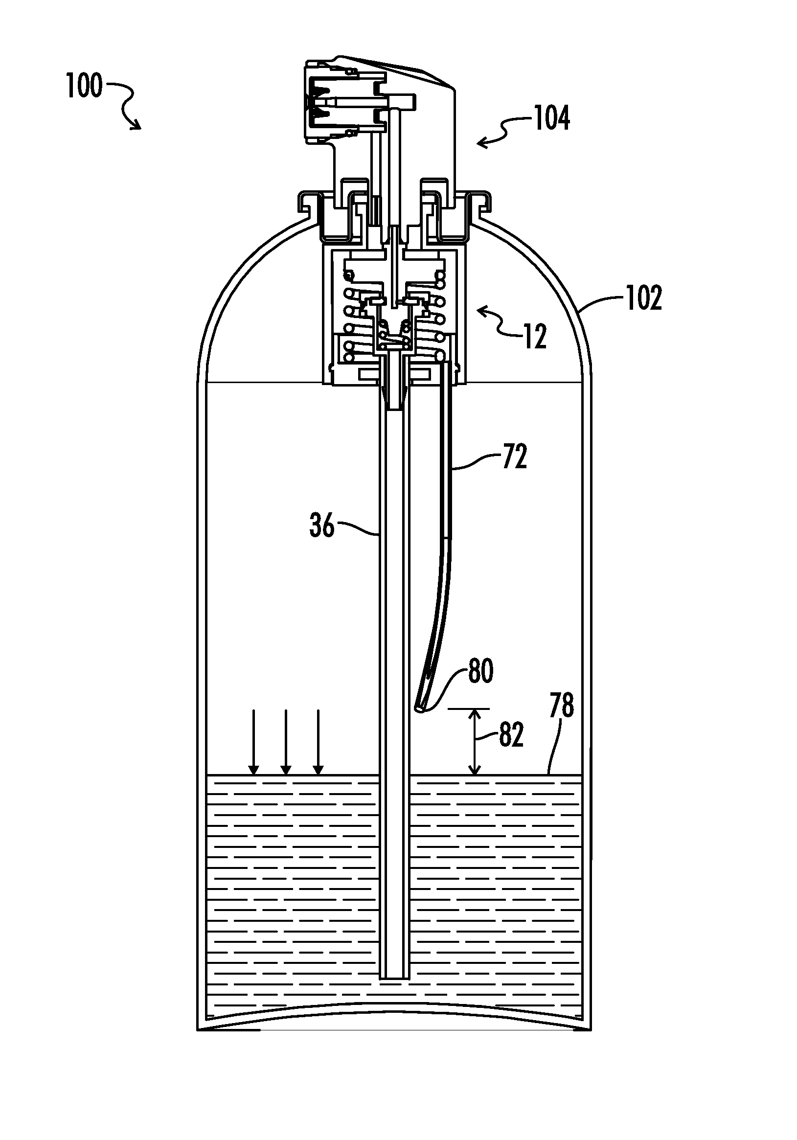
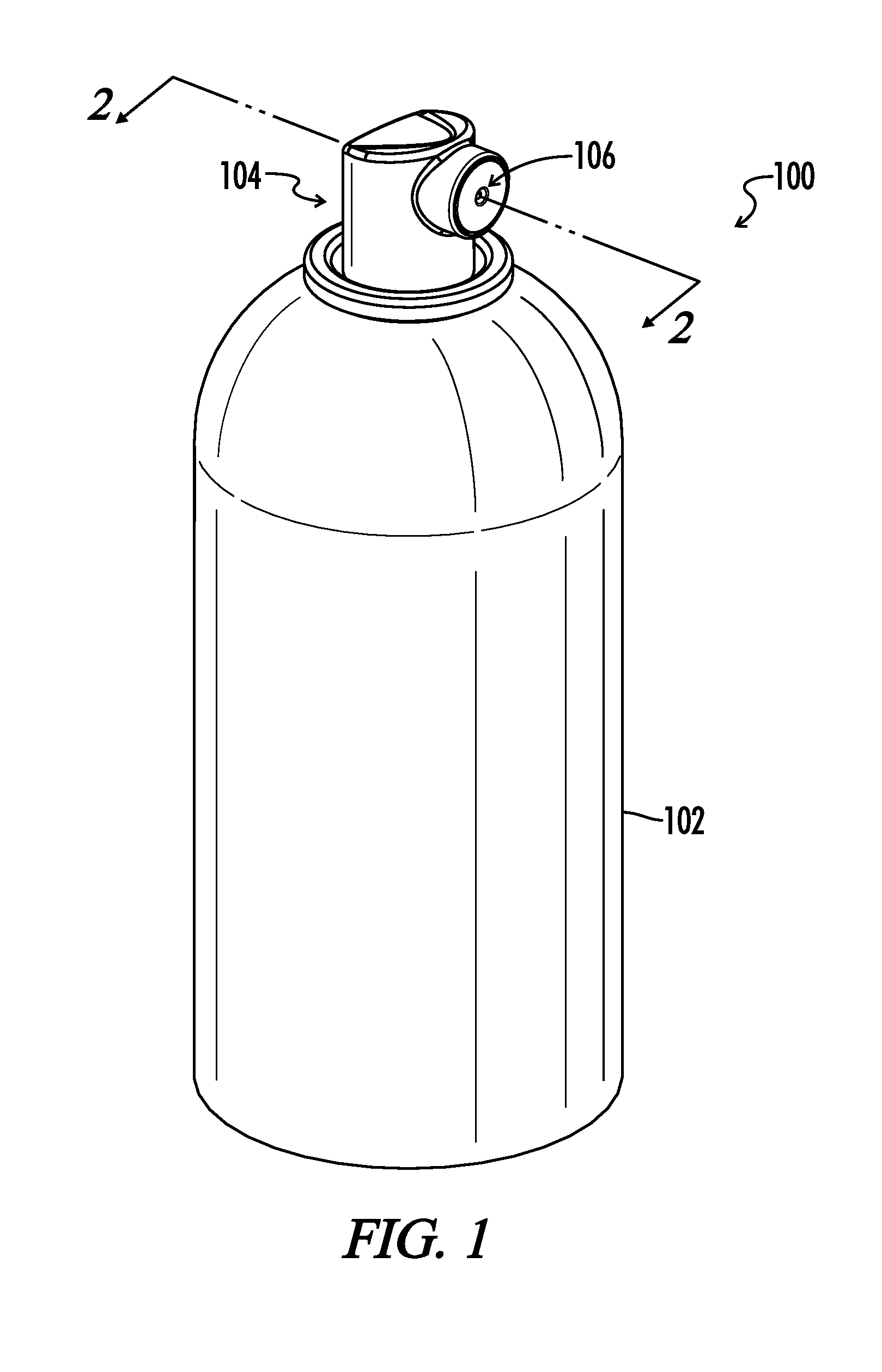
[0031]Referring now to the drawings, FIG. 1 illustrates an embodiment of a dispensing device 100. Dispensing device 100 generally includes a container 102 attached to a dispensing head 104. Dispensing head 104 includes an ejection opening 106 from which a liquid product stored in container 102 may be dispensed, or ejected. During use, a user may depress dispensing head 104 relative to container 102 to cause the liquid product stored in container 102 to be ejected from dispensing head 104 and more particularly from an ejection opening 106 on dispensing head 104.

[0032]Although the figures illustrate an embodiment of a dispensing device including spray direction oriented at a right angle relative to the actuation direction of the dispensing head, other embodiments not illustrated encompassed within the scope of the present invention include spray directions that are oriented at other angles relative to the actuation direction. For example, in additional embodiments, the device is confi...


PUM


Abstract

A device for dispensing a liquid product as an atomized spray includes a container, a depressible dispensing head for initiating emission of the spray from the device and for terminating emission of the spray from the device, and a sequential delivery valve attached to the dispensing head. The dispensing device is configured to initiate flow of gas only into the dispensing head first when the dispensing head is depressed from a first axial position to a second axial position. When the dispensing head is depressed further toward the container to a third axial position, the dispensing device allows both liquid and gas to travel from the container into the dispensing head. When the dispensing head is released from the third axial position back to the first axial position, the dispensing device first stops flow of liquid into the dispensing head before stopping flow of gas into the dispensing head.

Description

BACKGROUND[0001]1. Technical Field[0002]The present invention relates generally to devices and methods for creating sprays and more particularly to devices and methods for creating atomized spray of liquid product.[0003]2. Related Art[0004]Devices for dispensing liquids are generally known in the art. Such conventional devices generally include a container for storing a liquid product and a means for ejecting the liquid product from the container through a dispensing head or a nozzle. Such conventional delivery means often include a reservoir of pressurized gas stored in the container. The pressurized gas serves as a propellant for forcing the liquid product out of the container.[0005]Such conventional devices often include a dispenser head including a depressible pump or actuator for manual manipulation by a user. By depressing the dispenser head, a user may selectively open a valve or other mechanism that allows the pressurized gas, or gas propellant, to force the liquid product t...

Claims


Application Information

Patent Timeline
Patent Type & Authority Patents(United States)
IPC IPC(8): B65D83/00B67D7/00
CPCB65D83/20B65D83/48B05B7/0475B65D83/34
Inventor GANAN-CALVO, ALFONSO M.ASENSIO-CANO, MIGUEL A.FITO-PLANAS, ALVAROLOPEZ-SERRANO, JORGEPEREZ-VAQUERO, JAVIERBADOVICK, JEFFREY
Owner UNIV DE SEVILLA
Why Eureka
Try Eureka