Optical cavity structure of LED lighting apparatus

a technology of led lighting and optical cavity, applied in the field of light, can solve the problems of increasing material cost and power consumption, and achieve the effect of enhancing and achieving the desired luminance rang

Inactive Publication Date: 2014-12-02
YANG MEI LING +1
View PDF29 Cites 8 Cited by
  • Summary
  • Abstract
  • Description
  • Claims
  • Application Information

AI Technical Summary

Benefits of technology

[0003]An objective of the present invention is to overcome the drawbacks of known LED lighting apparatus requiring an increased number of LED chips and power input to achieve an enhanced illumination such that the increase in material costs and power consumption associated therewith can be prevented.
[0004]The present invention of an LED lighting apparatus is characterized in that an optical cavity is formed among and constructed by a base, a light reflector and a light cover altogether. With the structure of the optical cavity provided, light emitted from the LED module on the base is gathered and further reflected by the light reflecting surface of the light reflector such that the desired luminance range can be achieved to increase the illumination thereof.
[0011]The light reflector of the present invention can be of an angle and shape selected for gathering and further reflecting light via the light reflecting surface thereof to achieve the enhanced and desired luminance range.

Problems solved by technology

Therefore, the increased use of the numbers of LED chips and associated power input directly leads to the increase of material costs and power consumption.

Method used


Image

  • Optical cavity structure of LED lighting apparatus
  • Optical cavity structure of LED lighting apparatus
  • Optical cavity structure of LED lighting apparatus

Examples


Embodiment Construction

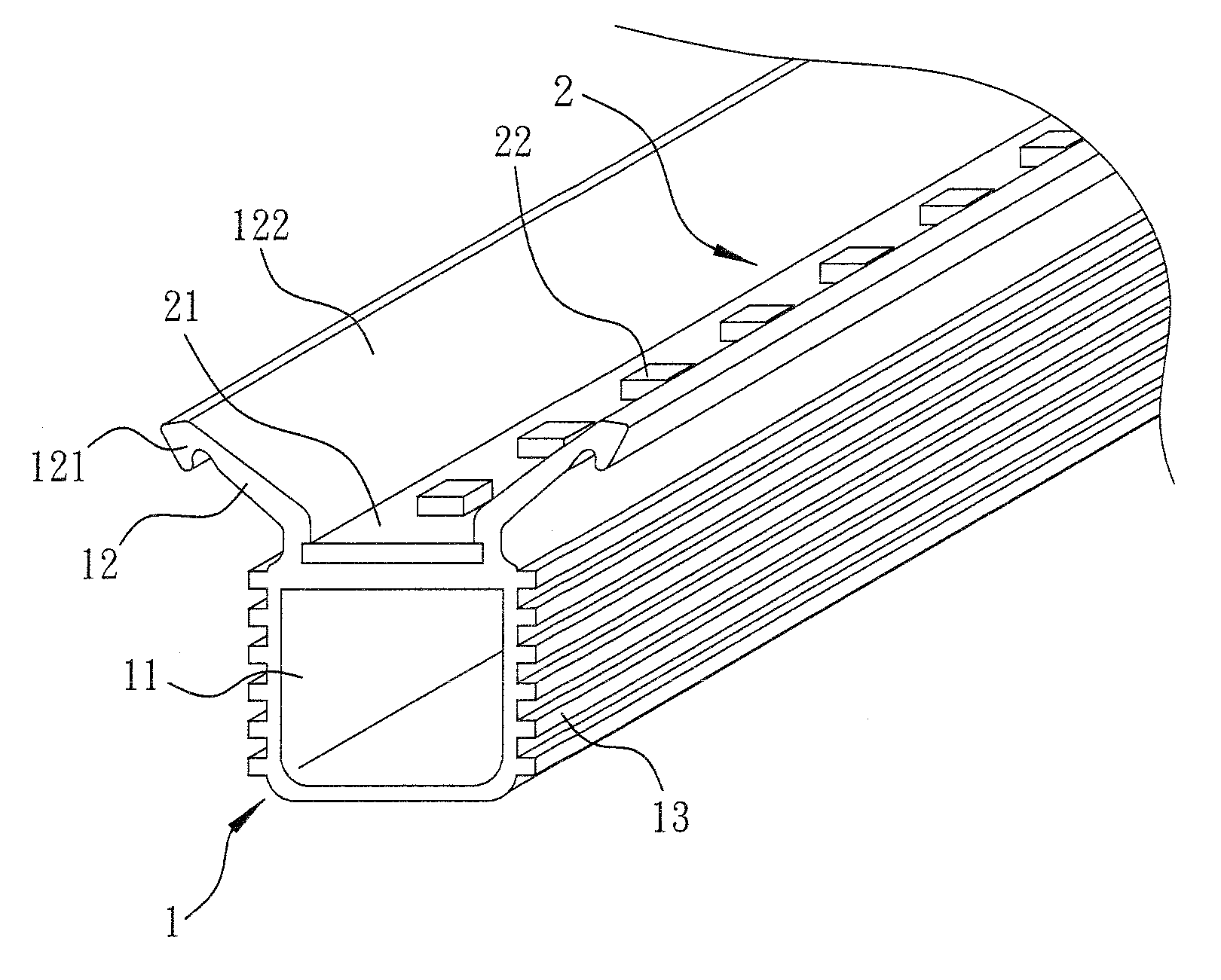
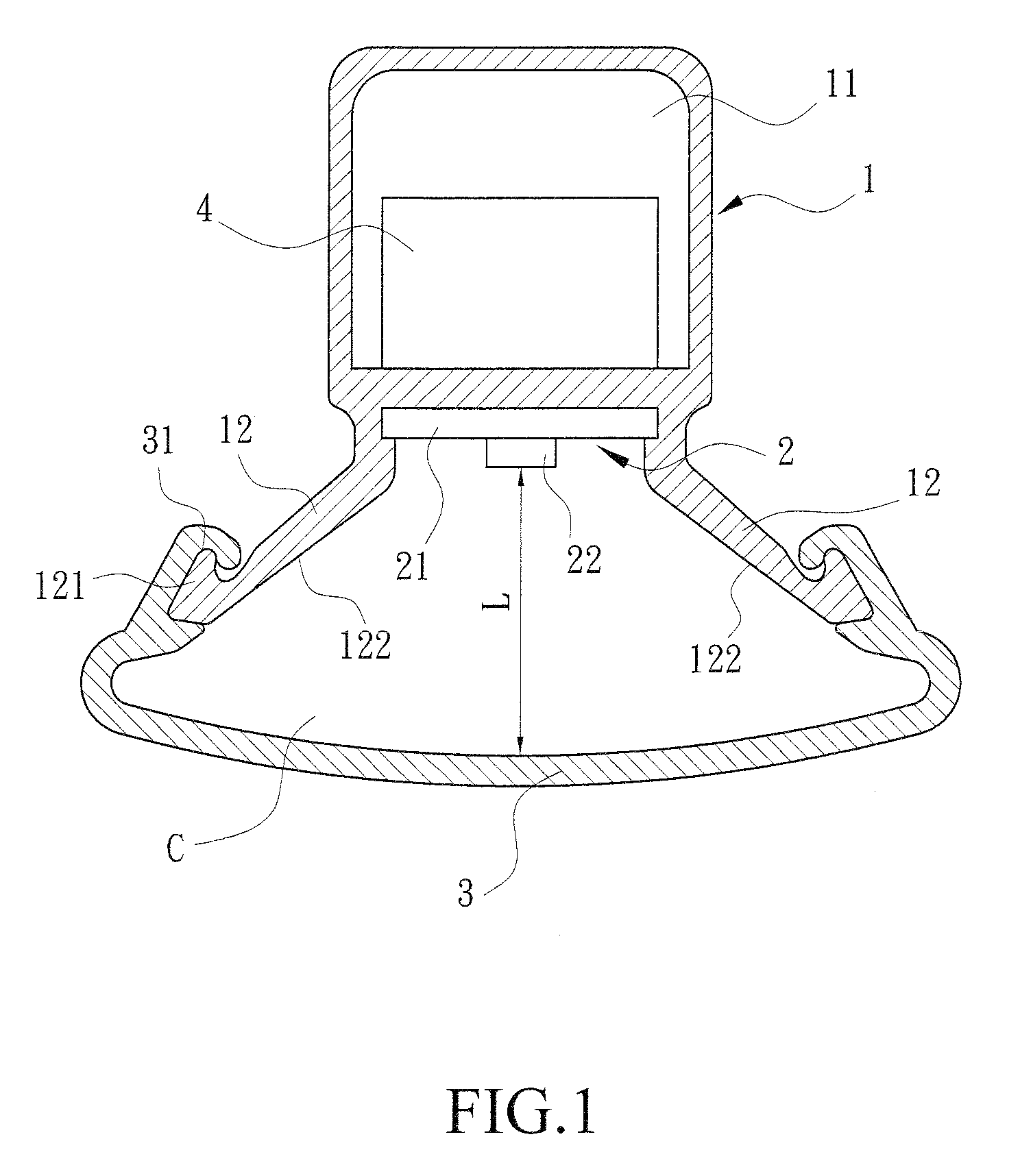
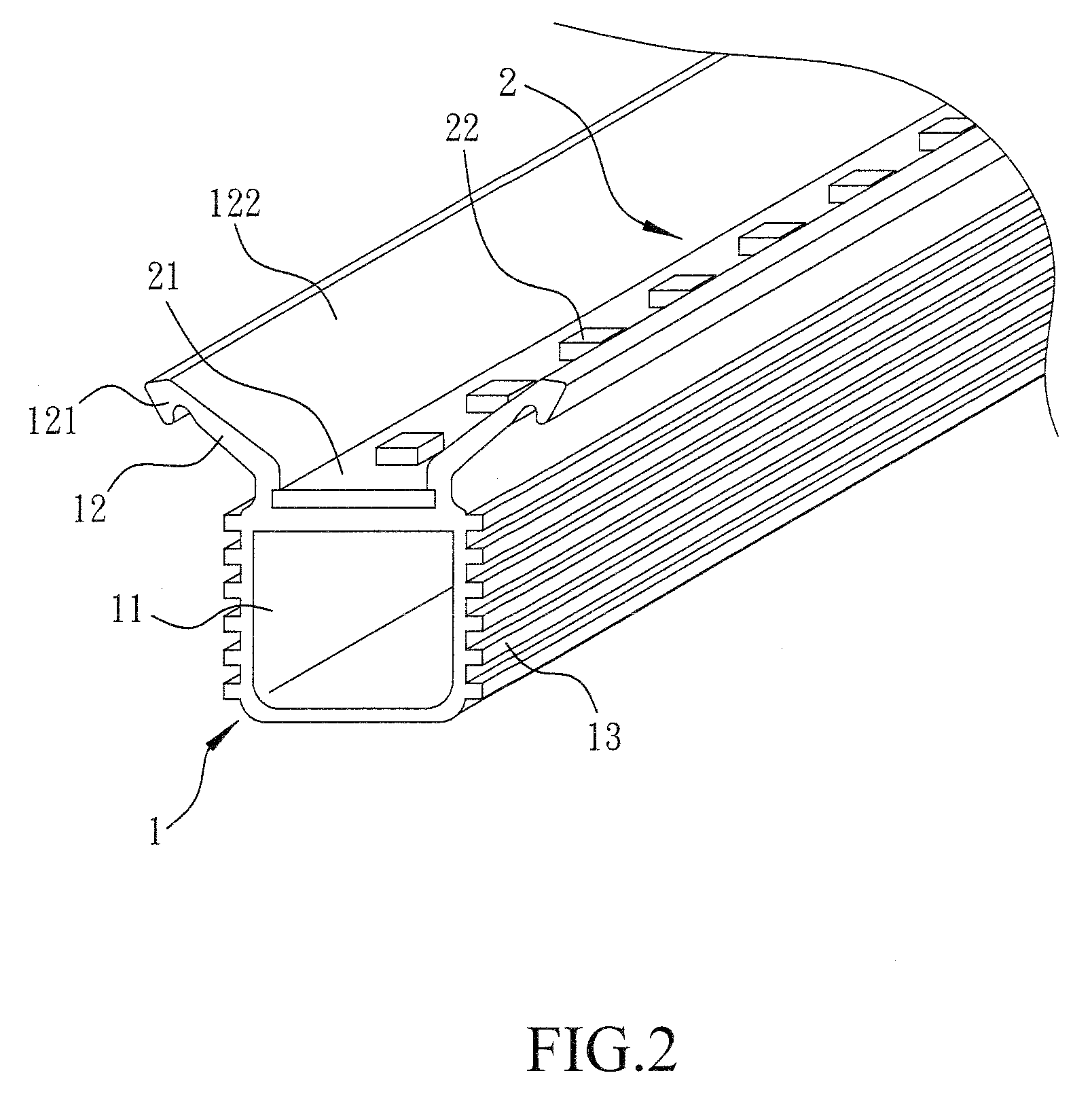
[0019]As shown in FIGS. 1 to 3, a first embodiment of the present invention comprises a base 1, a light reflector 12, a LED module 2 and a light cover 3. The base 1 is preferably made of aluminum material that is of relatively good heat conductivity and heat dissipation and can be produced by injection molding to have an elongated shape. A first end of the base 1 is formed of an internal space 11 to receive a power supply 4 therein; and a second end of the base 1 is provided for the installment or attachment of the LED module 2. In other words, the second end of the base 1 is configured to be in the direction of the emitted light of the LED chips 22 of the LED module 2 while the outer surface of the base 1 is formed with a plurality of fins 13 provided to absorb heat and increase the area of heat dissipation. Preferably, the light reflector 12 is provided on two symmetrical and opposite sides of the second end of the base 1 and integrally formed with the base 1 with an inclined angl...


PUM


Abstract

The present invention provides an optical cavity structure of an LED lighting apparatus comprising a base, a light reflector, LED module, and a light cover. The light reflector can be integrally formed with the base or an independent unit. An optical cavity is constructed by the base, light reflector and light cover altogether, and the LED module is attached to the base received within the optical cavity. The light reflector can be symmetrical with inclined angle or as a conical shape provided on two sides opposing to the direction of light from the LED module. The inner surface of the light reflector is a light reflecting surface. The light cover is attached to the light reflector. As a result, the light from the LED is gathered and reflected by the light reflecting surface via the angle and shape of the light reflector to achieve an enhanced luminance range and illumination.

Description

TECHNICAL FIELD OF THE INVENTION[0001]The present invention is related to an application and field of lighting, in particular, to a lighting apparatus utilizing the technology capable of enhancing the illumination thereof without increasing the number of light sources and the power consumption required.DESCRIPTION OF THE PRIOR ART[0002]A conventional lighting apparatus generally comprises a heat sink, a power supply and a LED module; wherein the LED module comprises a plurality of LED chips attached onto a circuit board to generate light upon current and power input to the circuit board thereof. The heat sink, in general, comprises a base and a plurality of fins configured on the base. The LED module is provided on one side of the base opposite to the fins such that as the heat generated by the LED module powered to emit light is conducted to the fins, air flow passing through the fins is able to dissipate the heat therefrom. Such known LED lighting apparatus includes a LED module t...

Claims


Application Information

Patent Timeline
Patent Type & Authority Patents(United States)
IPC IPC(8): F21V7/00F21V1/00F21V5/00
CPCF21V15/011F21V13/00F21Y2101/02F21V17/164F21V15/013F21V7/20F21V29/505F21V29/507F21Y2115/10
Inventor YANG, MEI-LINGCHANG, CHIN-CHIA
Owner YANG MEI LING
Why Eureka
Try Eureka