Automatic golf ball supply device

a golf ball and automatic technology, applied in golf accessories, sport apparatus, golf, etc., can solve the problems of increasing manufacturing cost, lowering productivity, and reducing production efficiency, so as to reduce production costs, minimize the height of the frame, and save weight, volume and installation of the product. a lot

Active Publication Date: 2015-03-10
CHO WAN JE
View PDF15 Cites 1 Cited by
  • Summary
  • Abstract
  • Description
  • Claims
  • Application Information

AI Technical Summary

Benefits of technology

[0019]The automatic golf ball supply device according to the present invention is advantageously characterized in that the weight, volume and installation of a product can be saved a lot in such a way to minimize the height of the frame, and it is possible to install the product of the preset invention without damaging a steel structure within the range of a conventional inter-floor thickness of a golf game practice place, and the productivity can be enhanced by reducing the number of parts, and the manufacture cost can be saved, thus minimizing the loss of driving force, thus maximizing the forced transfer force of the golf ball.

Problems solved by technology

The conventional automatic golf ball supply device has a problem that the height of the frame cannot be minimized because the height of the frame generally has at least a height higher than the sum of the height of the tee member and the height of the golf ball.
A driving force transfer device such as an additional belt or a gear or something and a forced transfer device are generally being used for the purpose of transferring a golf ball to the direction of a tee member; however the number of parts increases due to the driving force transfer device such as an additional belt or a gear or something, which results in disadvantageously lowering the productivity while increasing the manufacture cost.
The driving force might lose during the operation by way of the driving force transfer device, so the forced transfer force of the golf ball significantly decreases.

Method used


Image

  • Automatic golf ball supply device
  • Automatic golf ball supply device
  • Automatic golf ball supply device

Examples


Embodiment Construction

[0040]The automatic golf ball supply device according to embodiments of the present invention will be described with reference to the accompanying drawings.

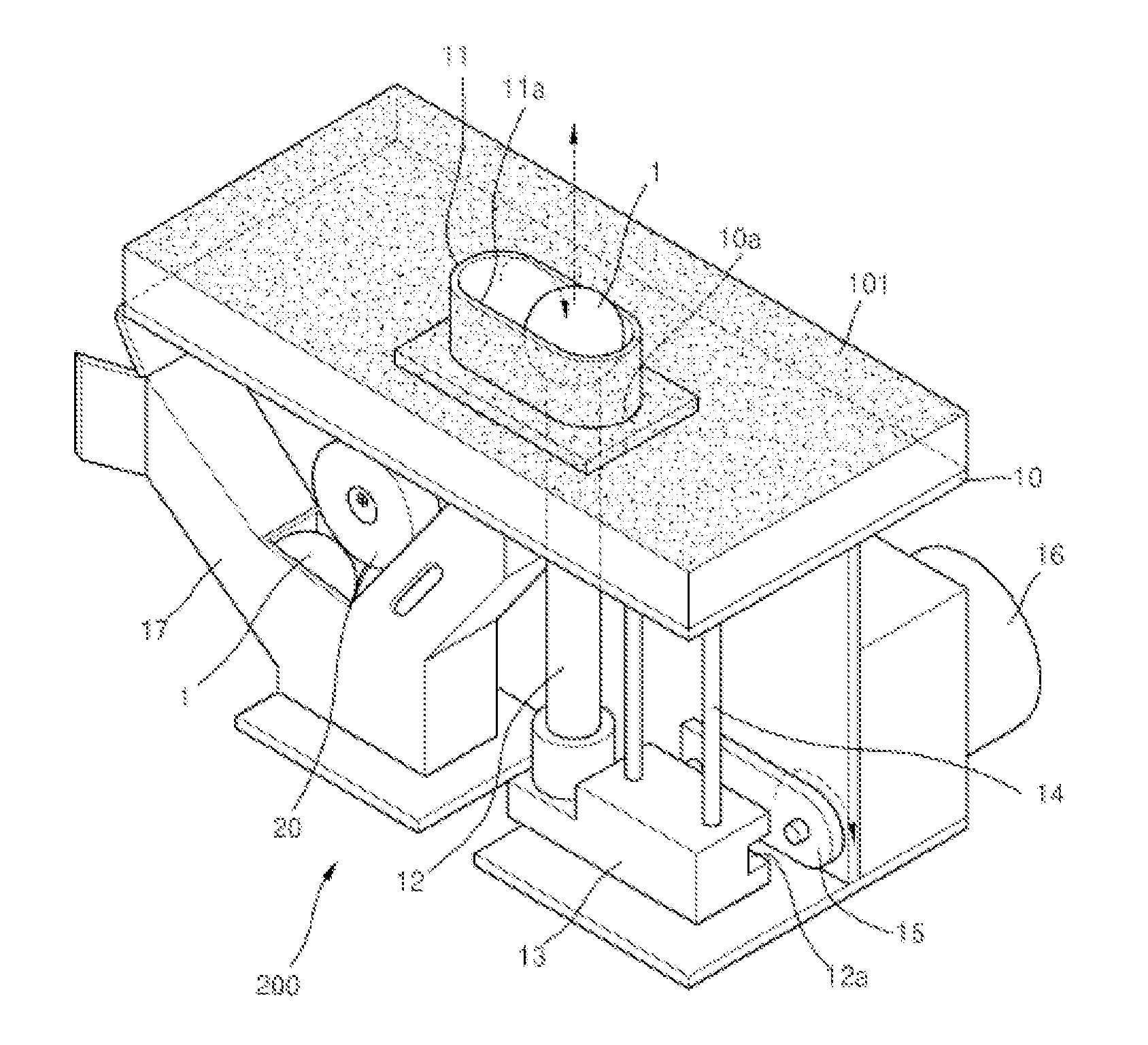
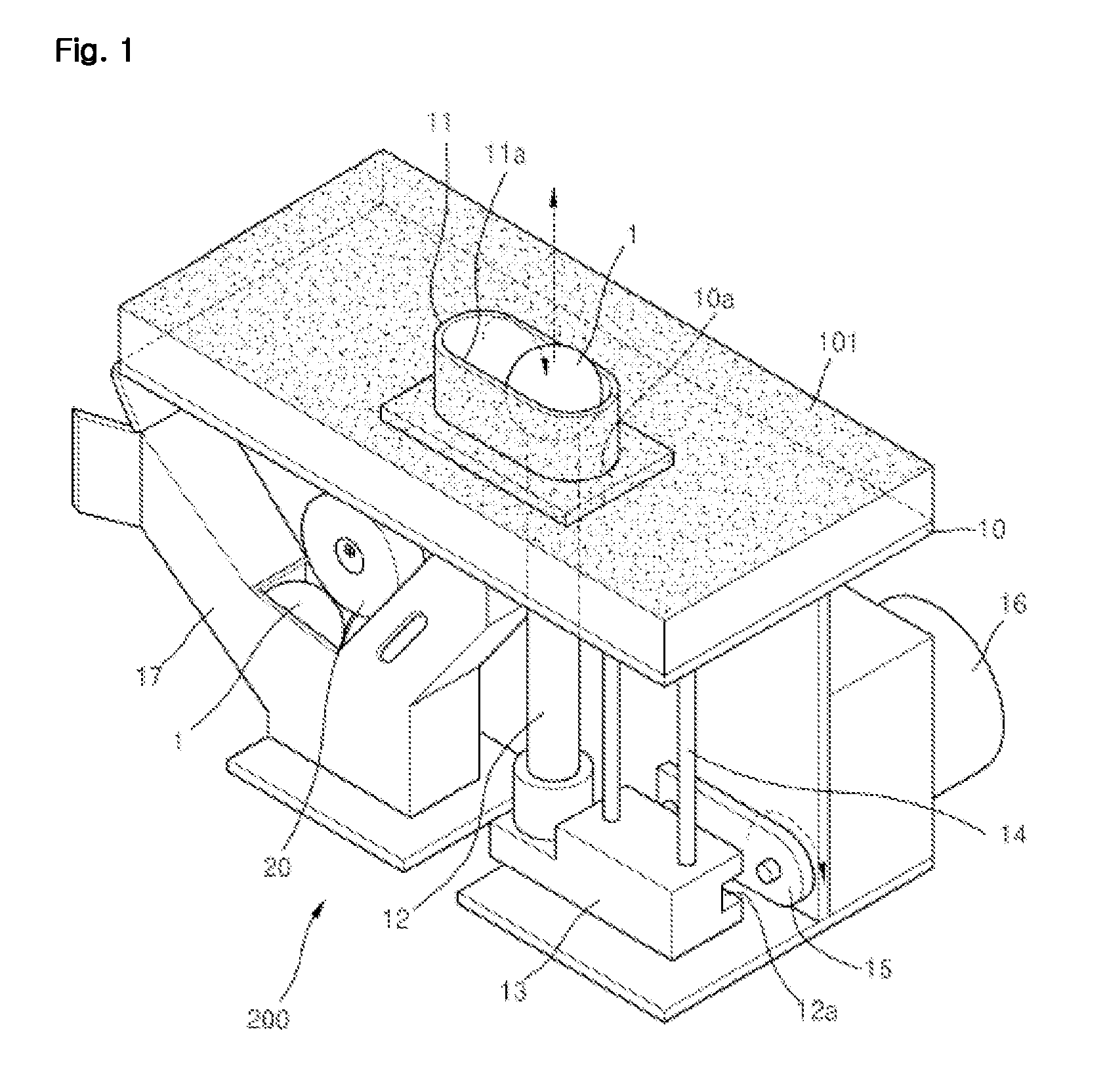
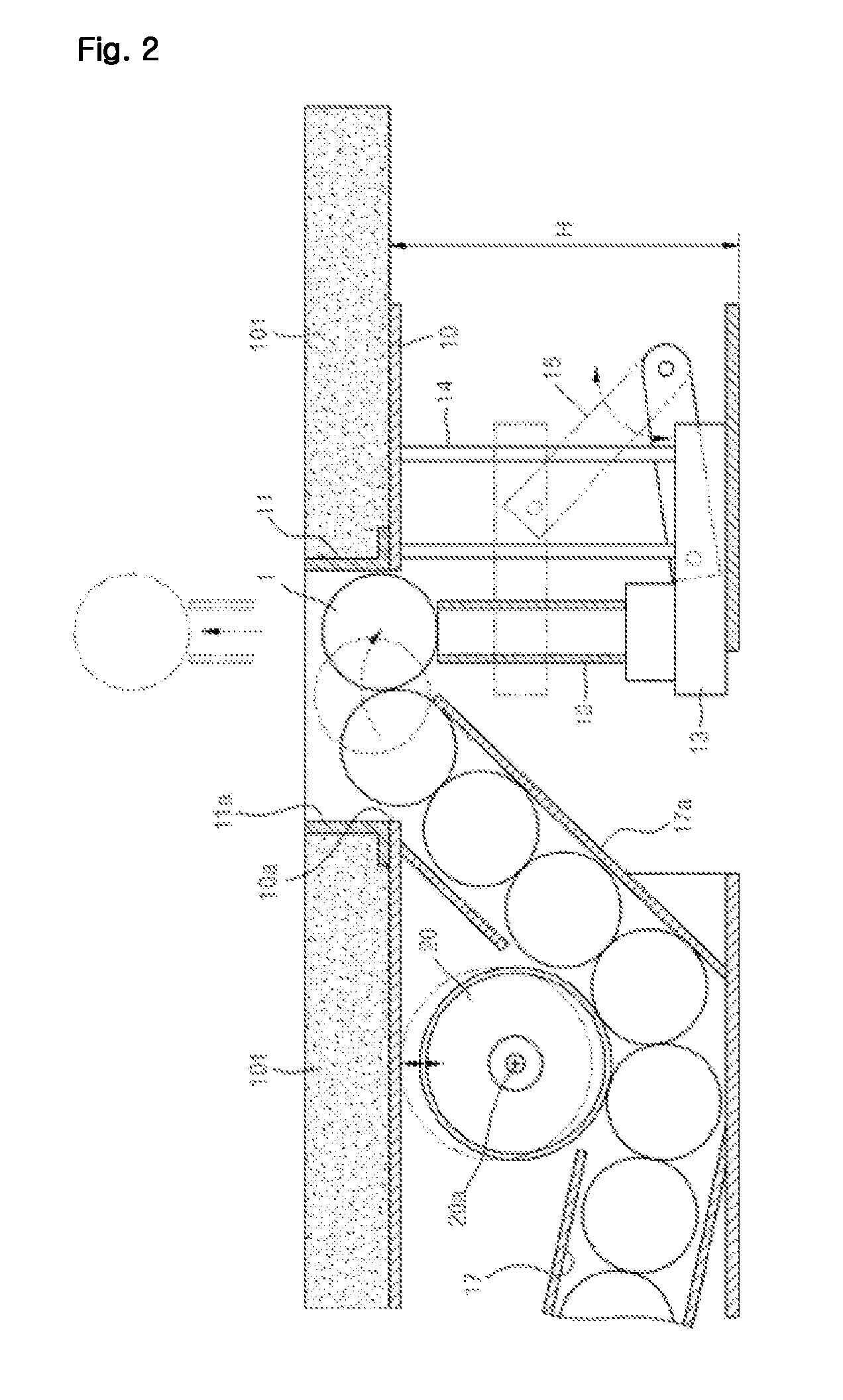
[0041]FIG. 1 is a perspective view illustrating an automatic golf ball supply device according to a preferred embodiment of the present invention. FIG. 2 is a left side cross sectional view of FIG. 1. FIG. 3 is a right side cross sectional view of FIG. 1.

[0042]FIG. 7 is a view illustrating a front structure of an example of FIG. 1. FIG. 8 is a view illustrating a rear structure of FIG. 7. FIG. 9 is a view illustrating a golf ball transfer roller of FIG. 7. FIG. 10 is a view illustrating a rear structure of FIG. 9. FIG. 11 is an enlarged view of FIG. 10.

[0043]First of all, as shown in FIGS. 1 to 3, and FIGS. 7 to 11, the automatic golf ball supply device according to a preferred embodiment of the present invention is directed to automatically supplying a golf ball 1 at a portion where a user hits the golf ball 1 with a golf club a...


PUM


Abstract

The present invention relates to an automatic golf ball supply device, being an automatic golf ball supply device which automatically supplies golf balls to a position where the golf balls will be hit with a golf club by the user, which comprises: a frame on the upper part of which is formed a golf ball withdrawal hole; an ascending and descending mount which ascends and descends by means of a motor, and on the upper surface of which is provided a tee member where a golf ball rests, and which is provided so as to ascend and descend freely in the withdrawal hole direction following a guide provided in the frame; and a golf ball conveying loader which conveys golf balls towards the tee member of the ascending and descending mount as the outer circumferential surface rotates and makes contact with the golf balls inside a golf-ball-waiting chamber in such a way as to be able to push each golf ball and to rest the same on the tee member. Consequently, there are advantages in that the height of the frame can be minimized and there are great savings on the weight, volume and installation space of the product, and in that it is possible to reduce the number of parts and hence increase productivity and economize on production costs, and to minimize loss of motive force and so maximize the force with which the golf balls are conveyed.

Description

RELATED APPLICATIONS[0001]This application is a 371 application of International Application No. PCT / KR2010 / 009031, filed Dec. 16, 2010, which in turn claims priority from Korean Patent Application Nos. 10-2010-0123487, filed Dec. 6, 2010, and 10-2009-0125694, filed Dec. 16, 2009, each of which is incorporated herein by reference in its entirety.TECHNICAL FIELD[0002]The present invention relates to an automatic golf ball supply device, and in particular to an automatic golf ball supply device which makes it possible to supply a plurality of golf balls in sequence at a portion where a user hits a golf ball with a golf club in a golf game practice place or the like and makes it possible to significantly lower the height of a frame and to easily perform a forced transfer of a golf ball.BACKGROUND ART[0003]Golf is a sport in which a game winner is generally decided by a player who finishes all the rounds with less hits attempted to insert a small, round golf ball into a targeted hole. T...

Claims


Application Information

Patent Timeline
Patent Type & Authority Patents(United States)
IPC IPC(8): A63B69/36A63B57/00
CPCA63B57/0006A63B47/002A63B69/36
Inventor CHO, WAN JE
Owner CHO WAN JE
Why Eureka
Try Eureka