Optical distance measuring device and method for optical distance measurement

a technology of optical distance measurement and measuring device, which is applied in the direction of distance measurement, instruments, and using reradiation, can solve the problems of large amount of unwanted background light detected, large amount of radiation energy, and large amount of unwanted background light, so as to reduce radiation energy and increase the measuring speed

a technology of optical distance measurement and measuring device, which is applied in the direction of distance measurement, instruments, and using reradiation, can solve the problems of large amount of unwanted background light detected, large amount of radiation energy, and large amount of unwanted background light, so as to reduce radiation energy and increase the measuring speed

US9395440B2Active Publication Date: 2016-07-19VOLKSWAGEN AG

Image

  • Optical distance measuring device and method for optical distance measurement
  • Optical distance measuring device and method for optical distance measurement
  • Optical distance measuring device and method for optical distance measurement

Examples


Embodiment Construction

[0035]Regarding the following description of the embodiments of the present invention, it should be noted that, in order to simplify matters, the same reference numerals are used in the entire description in the different figures for functionally identical or equally acting, or functionally equal, equivalent elements.

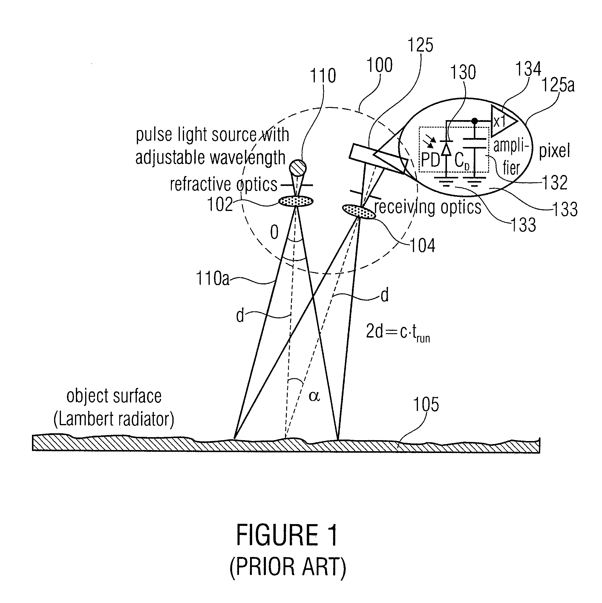
[0036]FIG. 1 illustrates a schematical arrangement of a measurement system 100 for optical distance measurement and a possible pixel architecture 125a of an image sensor. For obtaining distance or depth information, a target object 105 is irradiated with a pulsed laser 100. In a phase-locked manner thereto, the exposure of an integrating photoreceiver array in the image sensor 125 begins. The distance d of the sensor to the irradiated object 105 is decisive for the runtime of the light pulse 110a emitted by the laser source 110 and hence for the optical power measured by the receiver 125 in a fixed exposure time window. The optical distance measuring device 100 can, for...


PUM


Abstract

The present invention describes an optical distance measuring device having a pulsed radiation source that is implemented to transmit, in a temporally contiguous radiation pulse period, a radiation pulse having a pulse duration tp that is shorter than the radiation pulse period, and to transmit no radiation pulse in a temporally contiguous dark period. Further, the optical distance measuring device includes a detector for detecting different amounts of radiation in two overlapping detection periods during the radiation pulse period to capture reflections of the radiation pulse at an object surface and a background radiation and / or in two overlapping detection periods during the dark period to capture background radiation. The optical distance measuring device further includes an evaluator determining a signal depending on a distance of the optical distance measuring device to an object based on the detected amount of radiation. Further, the present invention provides a method for optical distance measurement and for multiple sampling.

Description

CROSS-REFERENCE TO RELATED APPLICATION[0001]This application is a U.S. National Phase entry of PCT / EP2009 / 002570 filed Apr. 7, 2009, and claims priority to German Patent Application No. 10 2008 018718.6 filed Apr. 14, 2008, each of which is incorporated herein by references hereto.BACKGROUND OF THE INVENTION[0002]The present invention relates to an optical distance measuring device and a method for optical distance measurement, as used, for example, in 3D cameras.[0003]The technical field of application of the present invention is manifold, as will be described below. Complementary metal oxide semiconductor (CMOS) image sensor technology provides effective options for recording measurement signals in real time at high speed. This is of great importance when capturing three-dimensional (3D) distance images. Pulse runtime methods and methods with continuously modulated light serve here for contactless depth detection. For this, the residual intensity of an infrared laser light reflect...

Claims


Application Information

Patent Timeline
19 Jul 2016
Publication
US9395440B2
IPC
G01C3/08; G01S17/10; G01S7/487; G01S17/89; H01J40/14; G01S17/18; G01S17/894
CPC
G01S17/107; G01S7/487; G01S17/89; G01S17/18; G01S17/894; G01C3/08
Inventors
SCHREY, OLAF; BROCKHERDE, WERNER