Electro-optical device, method of manufacturing electro-optical device, and electronic apparatus

a manufacturing method and electrooptical technology, applied in the field of electrooptical devices, can solve the problems of difficult to sufficiently suppress the temperature rise of the element substrate, the electro-optical device's life reduction, and the malfunction or the reduction of life, etc., to achieve the effect of efficient release of the heat of the light-transmitting cover

Active Publication Date: 2016-10-11
SEIKO EPSON CORP
View PDF7 Cites 3 Cited by
  • Summary
  • Abstract
  • Description
  • Claims
  • Application Information

AI Technical Summary

Benefits of technology

[0009]An advantage of some aspects of the invention is to provide an electro-optical device, a method of manufacturing an electro-optical device, and an electronic apparatus which are capable of more efficiently releasing the heat of a light-transmitting cover disposed on a side on which light is applied to mirrors.
[0012]In the electro-optical device according to the invention, the light transmits through the light-transmitting cover, and is incident on the mirror. Light reflected from the mirrors transmits through the light-transmitting cover, and is emitted. For this reason, the temperature of the light-transmitting cover tries to increase due to the applied light. Meanwhile, in the electro-optical device according to the invention, since the first metal portion in contact with the light-transmitting cover and the element substrate are formed, it is possible to more efficiently release the heat of the light-transmitting cover through the first metal portion, the element substrate and the substrate. Accordingly, since the temperature rise of the electro-optical device can be suppressed, it is possible to suppress the malfunction or the life reduction of the electro-optical device.
[0013]In the aspect of the invention, it is preferable that the first metal portion is formed in a frame shape that surrounds the periphery of the mirrors in planar view. In such a configuration, it is possible to more efficiently release the heat of the light-transmitting cover through the first metal portion, the element substrate and the substrate.
[0014]In the aspect of the invention, it is preferable that the electro-optical device further includes a second metal portion that is in contact with the substrate and the light-transmitting cover. In such a configuration, it is possible to more efficiently release the heat of the light-transmitting cover to the substrate through the second metal portion. Accordingly, since the temperature rise of the electro-optical device can be suppressed, it is possible to suppress the malfunction or the life reduction of the electro-optical device.
[0020]The aspect of the invention may adopt a configuration in which the electro-optical device further includes a sealing resin that is in contact with a lateral surface of the element substrate and a lateral surface of the light-transmitting cover between the second metal portion and the substrate. In such a configuration, it is possible to release the heat of the light-transmitting cover or the element substrate through the sealing resin. It is possible to prevent moisture from infiltrating into a portion where the mirror is provided by using the sealing resin.
[0021]The aspect of the invention may adopt a configuration in which the electro-optical device further includes a sealing resin that is in contact with a lateral surface of the element substrate and a lateral surface of the light-transmitting cover; and a light-transmitting inorganic material layer that is laminated on a surface of the light-transmitting cover opposite to a surface of the light-transmitting cover facing the mirror and a surface of the sealing resin opposite to a surface of the sealing resin facing the substrate, and is in contact with the substrate. In such a configuration, it is possible to release the heat of the light-transmitting cover or the element substrate through the sealing resin and the inorganic material layer. It is possible to prevent moisture from infiltrating by using the inorganic material layer and the sealing resin.

Problems solved by technology

Since such a temperature rise leads to the temperature rise of the electro-optical device, there is a concern that the malfunction or the life reduction of the electro-optical device occurs.
However, even though the transmission efficiency of the heat to the sealing resin 98 from the light-transmitting cover 29 is increased by the configuration shown in FIG. 18, since the transmission efficiency of the sealing resin 98 is low, there is a problem that it is difficult to sufficiently suppress the temperature rise of the element substrate 1.

Method used


Image

  • Electro-optical device, method of manufacturing electro-optical device, and electronic apparatus
  • Electro-optical device, method of manufacturing electro-optical device, and electronic apparatus
  • Electro-optical device, method of manufacturing electro-optical device, and electronic apparatus

Examples


embodiment 1

Projective Display Apparatus as Electronic Apparatus

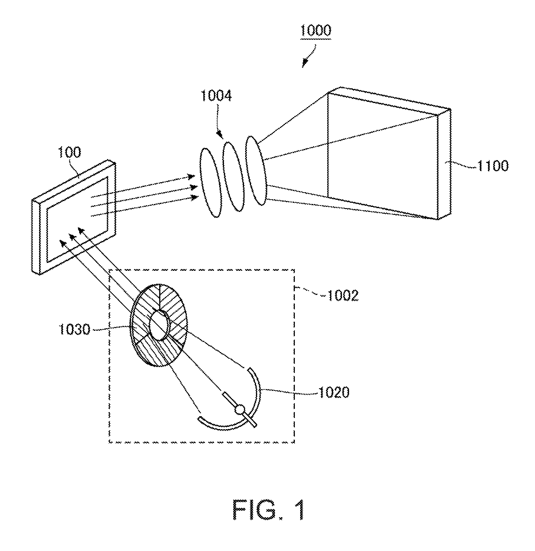
[0049]FIG. 1 is a schematic diagram showing an optical system of a projective display apparatus as an electronic apparatus to which the invention is applied. A projective display apparatus 1000 shown in FIG. 1 includes a light source unit 1002, an electro-optical device 100 that modulates light emitted from the light source unit 1002 according to image information, and a projection optical system 1004 that projects light modulated in the electro-optical device 100 as a projection image onto a projected object 1100 such as a screen. The light source unit 1002 includes a light source 1020, and a color filter 1030. The light source 1020 emits white light, the color filter 1030 emits color light beams with rotation, and the electro-optical device 100 modules incident light at a timing synchronized with the rotation of the color filter 1030. Instead of the color filter 1030, a fluorescent substrate that converts the light emitted from t...

embodiment 2

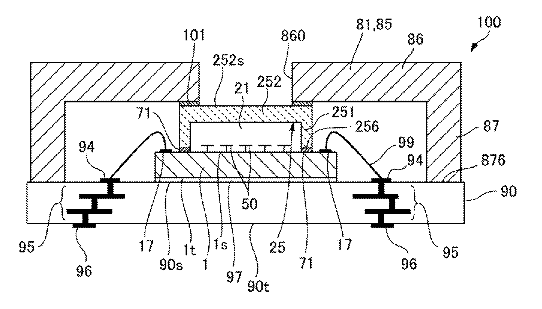
[0079]FIG. 8 is a sectional view of an electro-optical device 100 according to Embodiment 2 of the invention. FIGS. 9A to 9D are process sectional views showing a method of manufacturing the electro-optical device 100 according to Embodiment 2 of the invention. FIGS. 10A to 10C are process sectional views showing a process of mounting an element substrate 1 on a substrate 90 in the method of manufacturing the electro-optical device 100 according to Embodiment 2 of the invention. Since a basic configuration of the present embodiment is the same as that of Embodiment 1, common portions will be assigned the same reference numerals, and thus, the description thereof will be omitted.

[0080]Similarly to Embodiment 1, as shown in FIG. 8, in the electro-optical device 100 of the present embodiment, the element substrate 1 in which a plurality of mirrors 50 is formed on one surface 1s is mounted on a mounting surface 90s of the substrate 90 made from a ceramic substrate through an adhesive la...

embodiment 3

[0097]FIG. 12 is a sectional view of an electro-optical device 100 according to Embodiment 3 of the invention. FIGS. 13A and 13B are process sectional views showing a method of manufacturing the electro-optical device 100 according to Embodiment 3 of the invention. FIGS. 14A to 14C are process sectional views showing a process of mounting an element substrate 1 on a substrate 90 in the electro-optical device 100 according to Embodiment 3 of the invention. Since a basic configuration of the present embodiment is the same as that of Embodiment 1, common portions will be assigned the same reference numerals, and thus, the description thereof will be omitted.

[0098]Similarly to Embodiment 1, as shown in FIG. 12, in the electro-optical device 100 of the present embodiment, one surface 1s of the element substrate 1 in which a plurality of mirrors 50 is formed on one surface 1s is sealed by a light-transmitting cover 25. The element substrate 1 is mounted on a mounting surface 90s of the su...


PUM


Abstract

In an electro-optical device, a light-transmitting cover is disposed in mirrors, and when light is applied toward the mirrors through the light-transmitting cover, the temperature of the light-transmitting cover tires to increase due to the applied light. Here, in the electro-optical device, first metal portions that are in contact with the light-transmitting cover and the element substrate are formed. For this reason, it is possible to release the heat of the light-transmitting cover to a substrate through the first metal portions and the element substrate.

Description

[0001]The entire disclosure of Japanese Patent Application No.2015-065935, filed Mar. 27, 2015 is expressly incorporated by reference herein.BACKGROUND[0002]1. Technical Field[0003]The present invention relates to a method of manufacturing an electro-optical device including a mirror, an electro-optical device, and an electronic apparatus.[0004]2. Related Art[0005]As an electronic apparatus, there has been known, for example, a projective display apparatus that displays an image on a screen by modulating light emitted from a light source by a plurality of mirrors (micromirrors) of an electro-optical device called a digital mirror device (DMD) and then enlargedly projecting the modulated light by a projection optical system. For example, the electro-optical device used in the projective display apparatus includes an element substrate 1 provided with mirrors 50 on one surface 1s, spacers 28 adhering to the one surface 1s of the element substrate 1 so as to surround the mirrors 50 in p...

Claims


Application Information

Patent Timeline
Patent Type & Authority Patents(United States)
IPC IPC(8): G02B26/08
CPCG02B26/0841G02B26/0816G03B21/00G03B21/2066B81B3/0081B81B7/0067G02B26/0833G03B21/008G03B21/16B81B3/00
Inventor HANAOKA, TERUNAO
Owner SEIKO EPSON CORP
Why Eureka
Try Eureka