Camera lens module

a technology for lens modules and cameras, applied in the direction of cameras, instruments, printers, etc., can solve the problems of difficult to achieve miniaturization of products, large size of camera modules, and device configuration, and achieve the effect of stably and accurately driving and controlling an optical image stabilizer

Active Publication Date: 2017-01-17
JAHWA ELECTRONICS
View PDF30 Cites 4 Cited by
  • Summary
  • Abstract
  • Description
  • Claims
  • Application Information

AI Technical Summary

Benefits of technology

[0011]Therefore, the present invention has been made in view of the above problems, and it is an object of the present invention to provide a camera lens module, which can achieve miniaturization of a product through a compact structure and, at the same time, stably and accurately drive and control an optical image stabilizer.
[0012]Another object of the present invention to implement a camera lens module equipped with an optical image stabilizer of high accuracy and preciseness by suppressing movement of a mover exceeding a driving range and unnecessary rotation of the mover in performing optical image stabilization.

Problems solved by technology

However, a size of the camera module generally increases and configuration of the device is complicated since a space is needed as much as to apply the four magnetic circuits, and thus it is difficult to achieve miniaturization of a product.
If the size or the number of parts of the mover is reduced for miniaturization of the module, there is a problem in that preciseness and promptness of the optical image stabilizer are lowered, and, particularly, since the mover is driven beyond a driving range in performing optical image stabilization by using a resultant force of orthogonal forces applied in the X and Y two axis directions or unnecessary rotation occurs when the mover is driven, accuracy of the correction is lowered.

Method used


Image

  • Camera lens module
  • Camera lens module
  • Camera lens module

Examples


Embodiment Construction

[0042]The preferred embodiment of the present invention will be hereafter described in detail, with reference to the accompanying drawings. In describing the present invention, if already known functions or specific descriptions of constitutions related to the present invention may make the spirit of the present invention unclear, detailed descriptions thereof will be omitted.

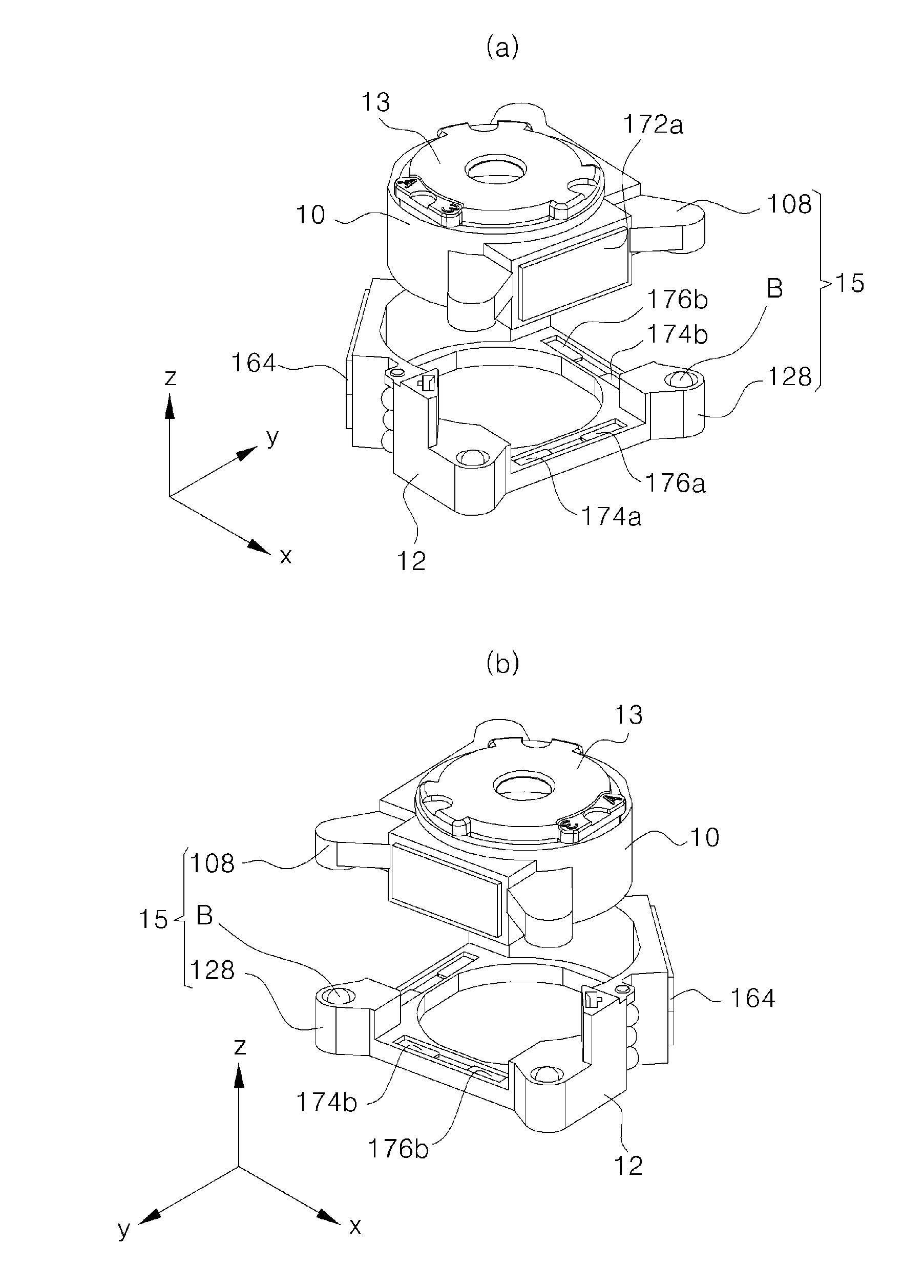
[0043]For the convenience of explanation, it will be described using a three-axis direction coordinate system, and in describing the figures, the Z-axis is defined as an optical axis direction, the X-axis is defined as an optical image stabilization direction orthogonal to the Z-axis optical axis direction, and the Y-axis is defined as another optical image stabilization direction orthogonal to the X-axis on the same plane.

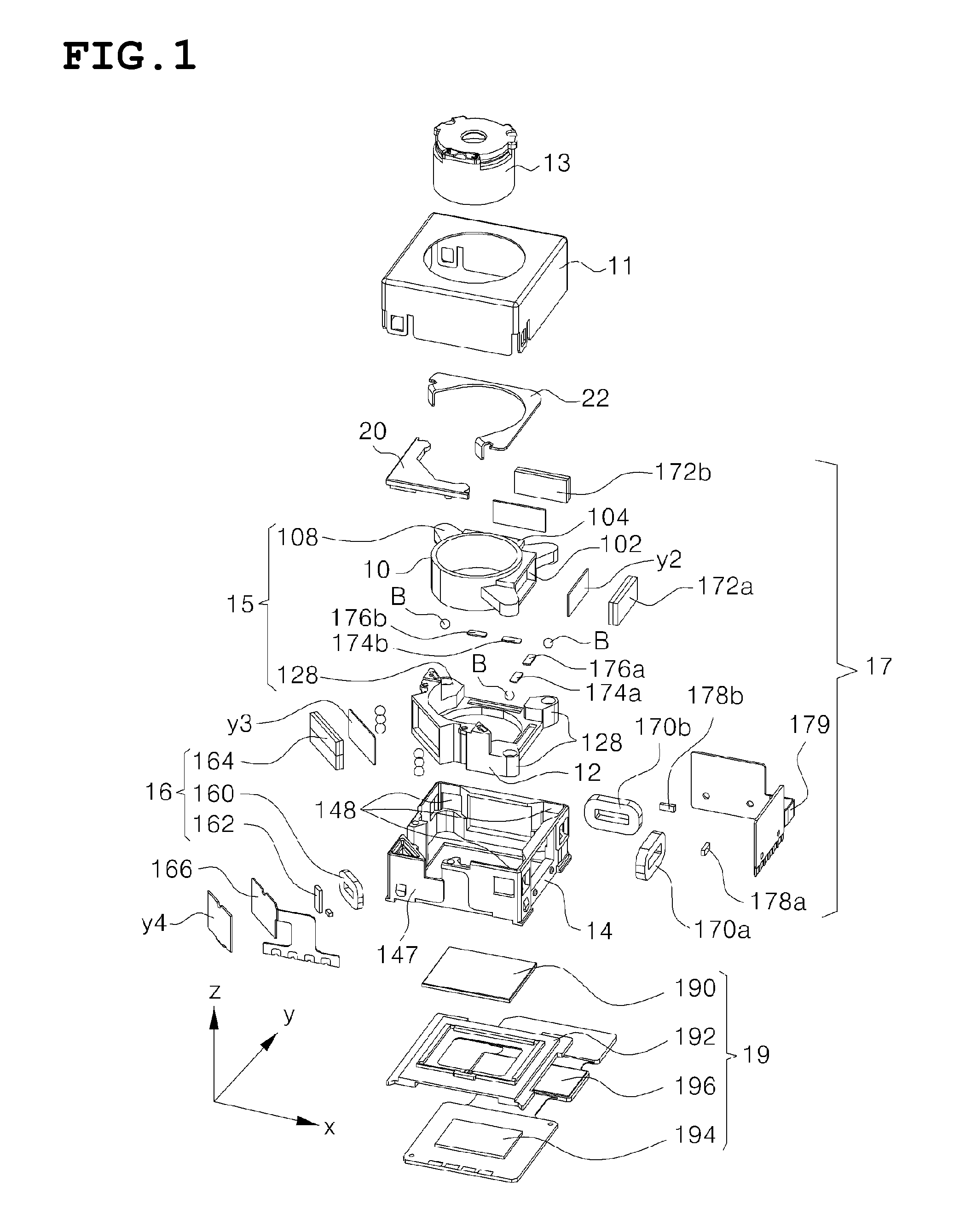
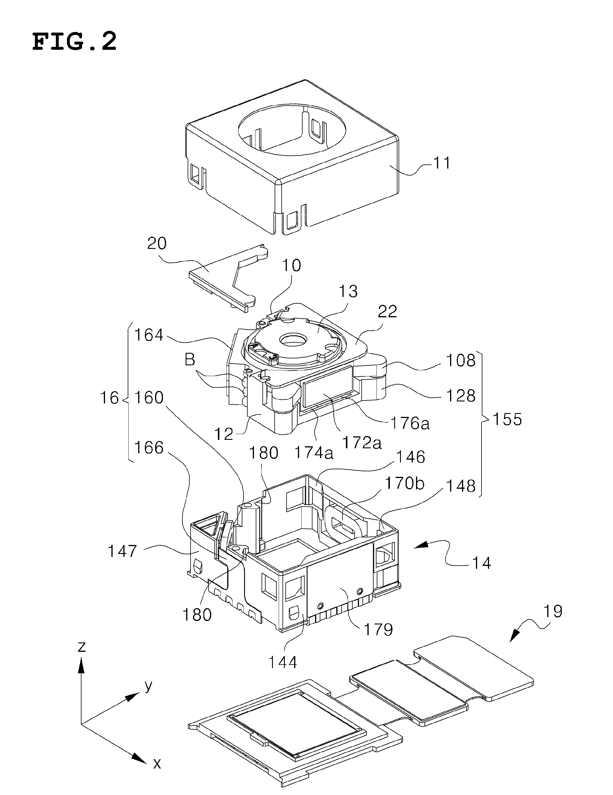
[0044]FIGS. 1, 2 and 3 are respectively an exploded perspective view, a partially exploded perspective view and a combined perspective view respectively showing a camera lens module according...


PUM


Abstract

A camera lens module according to an embodiment of the present invention is configured to include an optical image stabilizing carrier for accommodating a lens barrel; an autofocus carrier for mounting the optical image stabilizing carrier; a rolling unit for supporting a plane motion orthogonal to the optical axis of the optical image stabilizing carrier with respect to the autofocus carrier; a base for accommodating the autofocus carrier which mounts the optical image stabilizing carrier to advance and retreat the autofocus carrier in an optical axis direction; an optical image stabilizer driving unit; and an autofocus driving unit.

Description

CROSS-REFERENCE TO RELATED APPLICATIONS[0001]This application claims the benefit of Korean Patent Application No. 10-2014-0027013, filed with the Korean Intellectual Property Office on Mar. 7, 2014, the disclosure of which is incorporated herein by reference in its entirety.BACKGROUND OF THE INVENTION[0002]Field of the Invention[0003]The present invention relates to a camera lens module mounted on a portable mobile device, and more specifically, to a camera lens module equipped with an optical image stabilizer and an autofocus.[0004]Background of the Related Art[0005]A portable terminal such as a latest smart phone (hereinafter, referred to as a ‘mobile’) becomes multi-convergence as music, movies, a TV receiver, games and the like, as well as a simple telephone function, are mounted along with advancement of its technology, and one of factors leading to development of the multi-convergence is a camera lens module.[0006]The camera lens module mounted on the mobile is changed to a st...

Claims


Application Information

Patent Timeline
Patent Type & Authority Patents(United States)
IPC IPC(8): H04N5/225G02B27/64G03B5/00G03B3/10G03B13/36H04N5/232
CPCH04N5/2254G02B27/646G03B3/10G03B5/00G03B13/36H04N5/2253H04N5/2257H04N5/23264G03B2205/0007G03B2205/0053H04N5/2328H04N5/23212G02B5/208G02B7/006G02B7/09G03B5/04G03B2205/0069G03B2205/0015H04N23/57H04N23/55H04N23/54H04N23/67H04N23/682H04N23/685G03B30/00H04N23/6812H04N23/687G02B7/08
Inventor KIM, HEE SEUNGKIM, IN SOONOH, YO HAN
Owner JAHWA ELECTRONICS
Why Eureka
Try Eureka