Impingement cooling of turbine blades or vanes

a technology of turbine blades and cooling vanes, which is applied in the direction of blade accessories, machine/engines, blade manufacture, etc., can solve the problems of high cooling efficiency of aerofoils, limited cooling, distortion and possible failure of blades or vanes, etc., to reduce costs and construction efforts, increase cooling efficiency, and facilitate insertion apertures

Inactive Publication Date: 2017-05-16
SIEMENS AG
View PDF25 Cites 2 Cited by
  • Summary
  • Abstract
  • Description
  • Claims
  • Application Information

AI Technical Summary

Benefits of technology

[0016]Advantageously, the hollow aerofoil comprises a single cavity. But the invention could also be realized for a hollow aerofoil comprising two or more cavities each of them accommodating an impingement tube according to the invention and / or being a part of the fin-pin / pedestal cooling region, stated above, the hollow aerofoil comprises a trailing edge and a leading edge. In a preferred embodiment the protrusion section of the impingement tube extends in a direction oriented to the trailing edge. This results in an efficient use of the free space of the cavity and a direct cooling of this region. Moreover, the protrusion section could be provided with through holes. Thus, cooling medium guided via the impingement tube could be easily directed to the non-impingement pin-fin / pedestal cooling region.
[0033]In one non-limiting embodiment, the position of the trailing piece is locked into position in the hollow aerofoil via the leading piece thereby preventing the trailing piece to become dislocated from the hollow aerofoil. Particularly, the position of the trailing piece is locked into position in the hollow aerofoil via a press fit and / or a form fit resulting in a proper alignment of the tailing piece in the aerofoil. If the locking is facilitated via a form fit between the stepped contour of the impingement tube and the edge of the insertion aperture an advantageously loss proof arrangement could be gained.

Problems solved by technology

The effect of temperature on the turbine blades and / or stator vanes can be detrimental to the efficient operation of the turbine and can, in extreme circumstances, lead to distortion and possible failure of the blade or vane.
Problems arise when a size of an impingement cooling zone and thus the region of the aerofoil with the highest cooling efficiency, is limited by the size of the opening through which the impingement tube is inserted into the aerofoil or the blades or vanes, respectively.

Method used


Image

  • Impingement cooling of turbine blades or vanes
  • Impingement cooling of turbine blades or vanes
  • Impingement cooling of turbine blades or vanes

Examples


Embodiment Construction

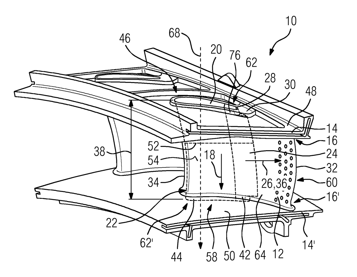
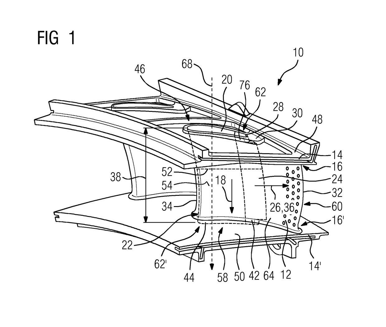
[0042]In the present description, reference will only be made to a vane, for the sake of simplicity, but it is to be understood that the invention is applicable to both blades and vanes of a turbine.

[0043]FIG. 1 shows in a perspective view a turbine assembly 10. The turbine assembly 10 comprises a basically hallow aerofoil 12, embodied as a vane, with two cooling regions, specifically, an impingement cooling region 58 and a fin-pin / pedestal cooling region 60. The former is located at a leading edge 34 and the latter at a trailing edge 32 of the aerofoil 12. Arranged at two sides 16, 16′ of the hollow aerofoil 12, wherein the two sides 16, 16′ are oriented basically perpendicular to a span wise direction 18 of the hollow aerofoil 12 and are positioned on opposed ends 62, 62′ of the aerofoil 12, are two wall segments 14, 14′ arranged. The wall segments 14, 14′ are regions 46 of an inner platform 48 and an outer platform 50. Each wall segment 14, 14′ has an insertion aperture 20 which ...


PUM

PropertyMeasurementUnit
distanceaaaaaaaaaa
temperatureaaaaaaaaaa
structuresaaaaaaaaaa

Abstract

A turbine assembly includes a basically hollow aerofoil. A wall segment may be arranged at a side of the aerofoil. An insertion aperture in the wall segment provides access to the aerofoil and an impingement tube may be inserted via the insertion aperture into the aerofoil to be located within the aerofoil and extend at least in a span wise direction of the aerofoil. A protrusion section of the impingement tube may extend in a direction basically perpendicular to the span wise direction over an edge of the insertion aperture. The protrusion section may be overlapped by at least a part of the wall segment. Adjacent to the protrusion section, an overlap section of the impingement tube is arranged to abut the edge of the insertion aperture. The protrusion section and the overlap section may be formed integrally with each other in one piece.

Description

CROSS REFERENCE TO RELATED APPLICATIONS[0001]This application is the US National Stage of International Application No. PCT / EP2012 / 060985 filed Jun. 11, 2012, and claims the benefit thereof. The International Application claims the benefit of European Application No. EP11171552 filed Jun. 27, 2011. All of the applications are incorporated by reference herein in their entirety.FIELD OF THE INVENTION[0002]The present invention relates to aerofoil-shaped turbine assembly such as turbine rotor blades and stator vanes. The present invention further relates to a method for assembling impingement tubes in such assemblies.BACKGROUND OF INVENTION[0003]Modern turbines often operate at extremely high temperatures. The effect of temperature on the turbine blades and / or stator vanes can be detrimental to the efficient operation of the turbine and can, in extreme circumstances, lead to distortion and possible failure of the blade or vane. In order to overcome this risk, high temperature turbines ...

Claims


Application Information

Patent Timeline
Patent Type & Authority Patents(United States)
IPC IPC(8): F01D5/18B23P15/04
CPCF01D5/18B23P15/04F01D5/189F05D2230/51F05D2230/53F05D2230/61F05D2250/70Y10T29/49337
Inventor MUGGLESTONE, JONATHAN
Owner SIEMENS AG
Why Eureka
Try Eureka