Three speed adjustable shock absorber having one or more microvalves

a technology of micro-valves and shock absorbers, which is applied in the direction of shock absorbers, vibration dampers, springs/dampers, etc., can solve the problems of not being able to adjust the conventional base valve assembly between soft, medium, firm performance settings, etc., and achieves firmer feel, soft and firm feel, and improved shock absorber structure

Active Publication Date: 2017-07-11
DUNAN MICROSTAQ
View PDF13 Cites 0 Cited by
  • Summary
  • Abstract
  • Description
  • Claims
  • Application Information

AI Technical Summary

Benefits of technology

[0009]This invention relates to an improved structure for a shock absorber that includes a base valve assembly with microvalves that allows the valves in the base valve assembly to be adjusted to meet driver preferred shock absorber performance or feel, such as a softer feel and a firmer feel. In one embodiment, the adjustable shock absorber includes a housing defining an enclosed working space. A wall is formed in the working space and separates the working space into first and second fluid chambers. A compression valve is formed in the wall and a microvalve is attached to the compression valve and is operable to control fluid flow through the compression valve.

Problems solved by technology

However, a conventional base valve assembly is not adjustable between desired soft, medium, and firm performance settings.

Method used


Image

  • Three speed adjustable shock absorber having one or more microvalves
  • Three speed adjustable shock absorber having one or more microvalves
  • Three speed adjustable shock absorber having one or more microvalves

Examples


first embodiment

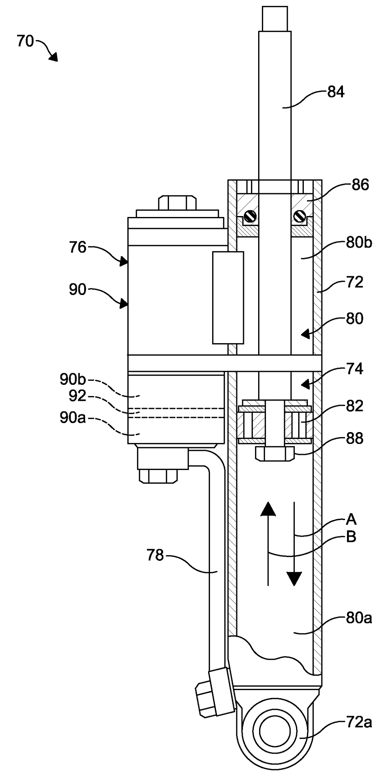
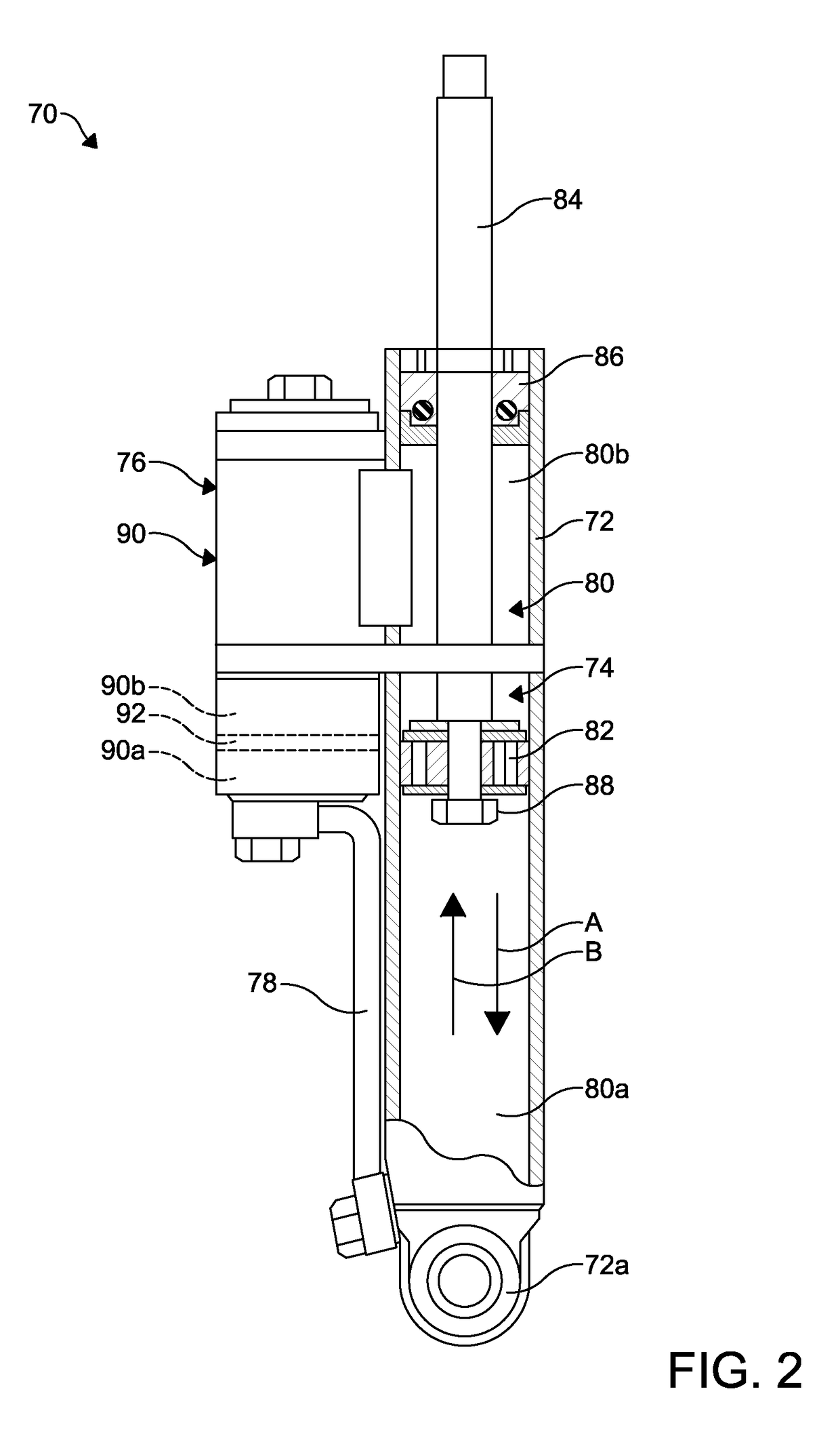
[0043]Referring to FIG. 4, a portion of an improved base valve assembly is shown at 100. The base valve assembly 100 is mounted within the housing 90 of the remote reservoir 76. The housing 90 defines an interior chamber or space 104. The base valve assembly 100 includes a base 106 which separates the interior space 104 into a first or lower working chamber 104a and an upper chamber or reservoir chamber 104b.

[0044]The base 106 is substantially cup shaped and has an annular side wall 106a and an end wall 106b. The side wall 106a is configured for sealing engagement with an inside surface of the housing 90. If desired, a resilient seal 108, such as an O-ring, may be disposed between the side wall 106a and the inside surface of the housing 90. In the illustrated embodiment, the seal 108 is disposed in a circumferential groove 106c formed in an outside surface of the side wall 106a. Alternatively, the seal 108 may be disposed in a circumferential groove (not shown) formed in an inside ...

second embodiment

[0046]As shown in FIGS. 5A and 5B, three compression valves 110A, 110B, and 110C are pre-set to operate in response to high speed and mid speed operation of the shock absorber. These pre-set configurations of the compression valves 110A, 110B, and 110C correspond to a soft, a medium, and a firm compression force displacement performance curves, and further correspond to soft, medium, and firm feel of the shock absorber, as experienced by a vehicle occupant. Additionally, a second compression valve 112 is configured to adjust the low speed characteristic of the performance curve. the replenishing valve 142 is shown in FIGS. 5A and 5B, and includes the pin 144 and a conical spring 147.

[0047]For example, for a soft ride or feel, the compression valve 110A may be configured with a relatively large diameter conduit 120 and with a spring 118 having a relatively low spring rate; i.e. a soft spring. Conversely, for a firm ride or feel, the compression valve 110B may be configured with a rel...


PUM


Abstract

An adjustable shock absorber includes a housing defining an enclosed working space. A wall is formed in the working space and separates the working space into first and second fluid chambers. A compression valve is formed in the wall and a microvalve is attached to the compression valve and is operable to control fluid flow through the compression valve.

Description

CROSS-REFERENCE TO RELATED APPLICATIONS[0001]This application claims the benefit of U.S. Provisional Application No. 62 / 047,382, filed Sep. 8, 2014, the disclosure of which is incorporated herein by reference.BACKGROUND OF THE INVENTION[0002]This invention relates to shock absorbers. In particular, this invention relates to an improved structure for an adjustable shock absorber that includes one or more microvalves to control fluid flow in a valve assembly arranged between working chambers in a shock absorber pressure tube and / or in a shock absorber reservoir.[0003]Shock absorbers are used in connection with automotive suspension systems to dampen vibrations, control rate of weight transfer, and improve vehicle comfort and performance. To perform these functions, shock absorbers are generally connected between the body and the suspension of the motor vehicle.[0004]Common shock absorbers for automobiles may be either a mono-tube design or a dual-tube design. In the mono-tube design, ...

Claims


Application Information

Patent Timeline
Patent Type & Authority Patents(United States)
IPC IPC(8): F16F9/44F16F9/34
CPCF16F9/44F16F9/34F16F9/512F16F9/065F16F9/067
Inventor BINGLE, COLIN B.
Owner DUNAN MICROSTAQ
Why Eureka
Try Eureka