

Clean lift
a lift and seat technology, applied in the field of hygienic lifting devices, can solve the problems of unsanitary and fertile breeding grounds, and achieve the effect of lowering the seat and facilitating the li
- Summary
- Abstract
- Description
- Claims
- Application Information
AI Technical Summary
Benefits of technology
Problems solved by technology
Method used
Image

Examples
Embodiment Construction
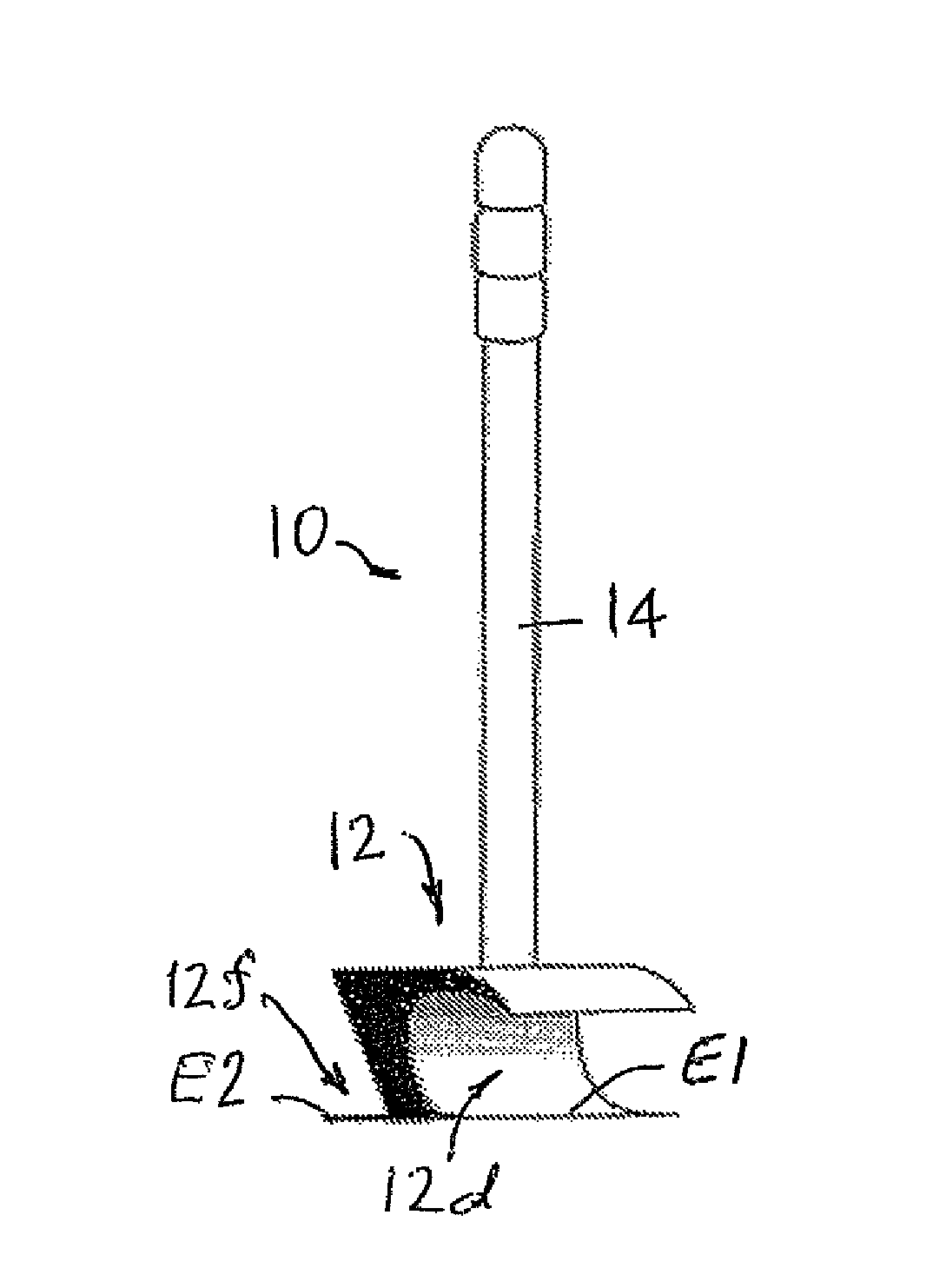
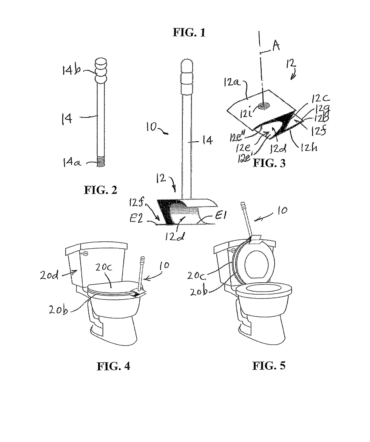
[0023]Referring now specifically to the Figures, in which identical or similar parts will be identified by the same reference numerals throughout, and first referring to FIG. 1, the device or unit in accordance with the present invention is generally designated by the reference numeral 10.
[0024]Also referring to FIGS. 2 and 3, the device 10 includes an engaging member 12 having a generally Z-shaped cross sectional configuration as shown in FIGS. 1 and 3. The member 12 includes a generally U-shaped curved wedge portion 12a and a straight wedge portion 12b, the portions 12a, 12b being joined by an inclined transition portion 12c. The curved wedge portion 12a forms a generally uniform U-shaped channel 12d that defines an arcuate surface 12e that includes both an upwardly facing surface portion 12e′ and a downwardly facing surface portion 12e″. The U-shaped channel is dimensioned to receive the edges of a toilet seat 20b and / or cover 20c. The straight portion 12b forms a generally trian...
PUM
 Abstract
Description
Claims
Application Information