
Crush type grid
A crushing grid and blade technology, which is applied in waterway systems, drainage structures, grain processing, etc., can solve the problems of reducing the performance of the water pump, the life of the impeller of the pump, reducing the water efficiency of the grid, and affecting the performance of the grid. Cost, unlimited visual space, beautification of the surrounding environment
Patent Information
- Authority / Receiving Office
- CN · China
- Patent Type
- Applications(China)
- Current Assignee / Owner
- Publication Date
- 2010-02-24
- Estimated Expiration
- Not applicable · inactive patent
Smart Images
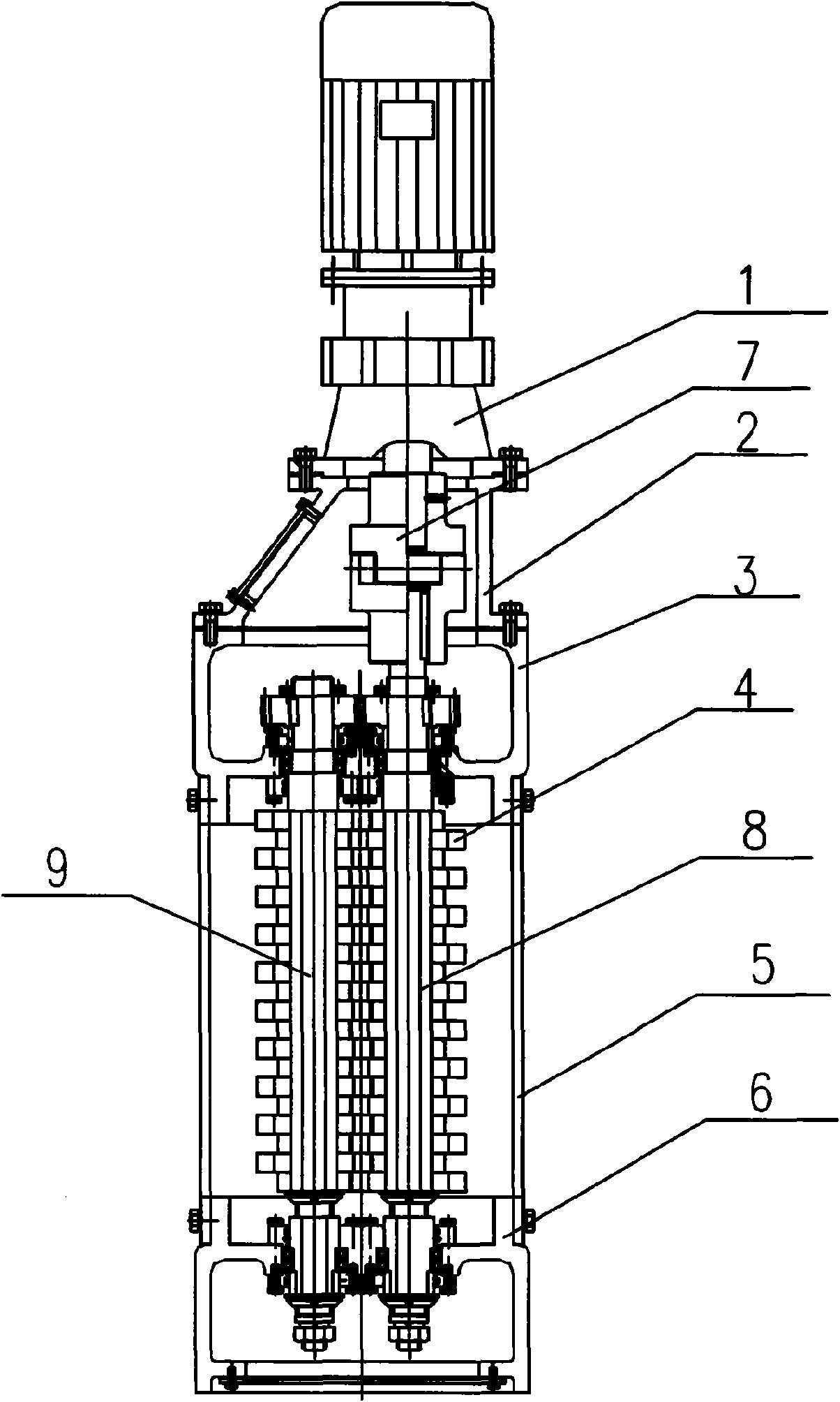
Figure 1 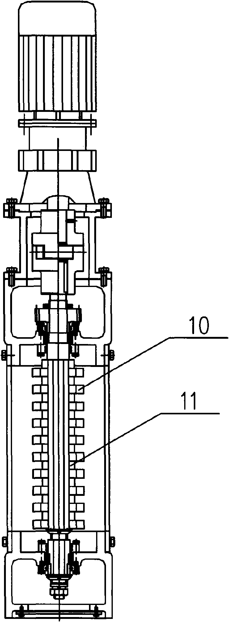
Figure 2 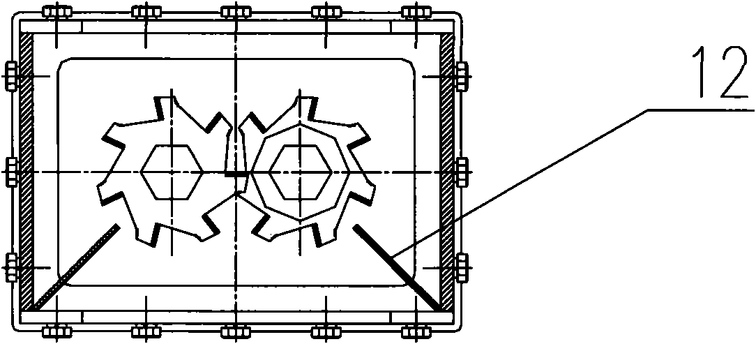
Figure 3
Abstract
Description
Technical field
[0001] The present invention is a device related to sewage treatment of sewers, in particular a crushing grid, that is, a grating with a grinder, and is mainly a device developed for crushing and processing solid waste mixed in the sewer. The equipment can crush solids such as cloth pieces, wood chips, empty bottles and cans mixed in the sewer to prevent the clogging of the sewer process equipment and ensure the normal operation of the sewer water treatment equipment. The equipment can be used in conjunction with the traditional pumping station or used alone, thus changing the application form of the traditional pumping station. Background technique
[0002] China's water resources per capita are small and their spatial distribution is uneven. With the acceleration of urbanization and industrialization in China, the demand for water resources is also increasing. In this context, the sewage treatment industry has become an emerging industry, currently in the same...
Examples
Embodiment Construction
[0031] Such as Figure 1-Figure 3 As shown, the crushed grille of the present invention mainly includes a geared motor 1, a coupling box 2, a transmission shaft box 3, a guide bracket 5, and a tail box 6, from top to bottom, and each component is vertically installed in sequence. among them:
[0032] The output shaft of the reduction motor 1 is connected to the upper end of the driving shaft 8 through a coupling 7; the driven shaft 9 and the driving shaft 8 are arranged in parallel, and the upper and lower ends of the two are respectively supported by the transmission shaft box 3 and the tail box through bearings 6, and the middle part passes through the entire diversion bracket 5, the front and rear sides of the diversion bracket 5 have diversion openings, and the two sides of the diversion opening are provided with guide plates 12 inward. The driven shaft 9 and the driving shaft 8 are connected by a transmission mechanism, and the coupling-type tool assembly 4 is respectively ...