
Protection circuit for three-wire system current output transmitter
A technology for protecting circuits and transmitters, applied in the direction of emergency protection circuit devices, emergency protection circuit devices, circuit devices, etc. for limiting overcurrent/overvoltage, and can solve the problem of overcurrent damage to diode D2, diode D2 or load resistance Damage, poor current limiting effect and other problems, to achieve the effect of reasonable and practical circuit and reduce the area of circuit board
Patent Information
- Authority / Receiving Office
- CN · China
- Current Assignee / Owner
- Publication Date
- 2010-03-10
Smart Images

Figure 1 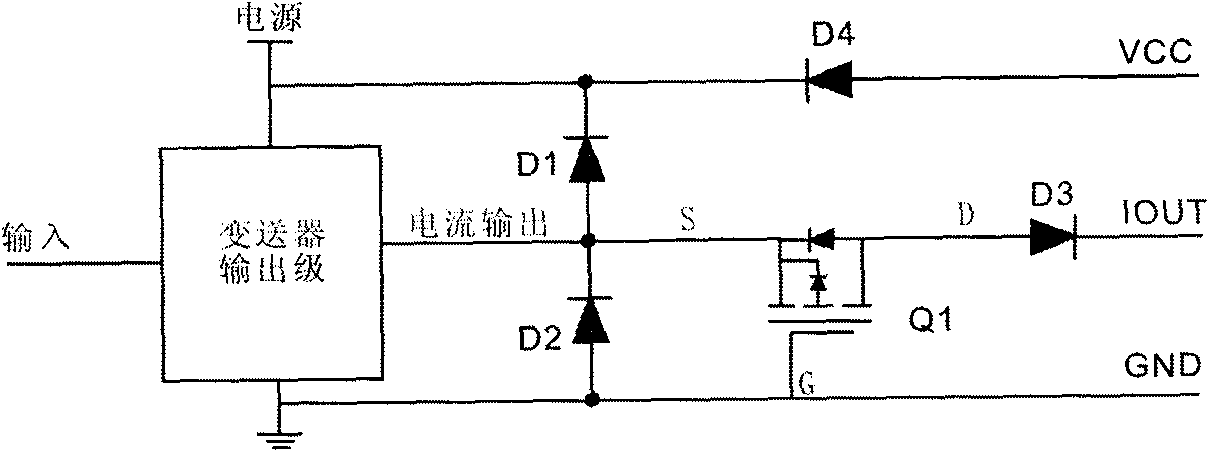
Figure 2
Abstract
Description
technical field
[0001] The invention relates to a port protection circuit of a three-wire current transmitter. Background technique
[0002] The current output type transmitter is widely used in industrial control sites, and its function is to amplify the signal (usually a voltage signal) of some sensors and convert it into a standard 4-20MA current signal. The working principle of this type of transmitter is generally to amplify the voltage signal first, and then convert the voltage to the current at the output stage. The output stage is generally composed of transistors or field effect transistors, and the actual application circuit diagram is shown in figure 1 .
[0003] The protection mechanism of the circuit is as follows:
[0004] Diodes D1 and D2 are clamping diodes to ensure that the level of the current output terminal is between GND-0.7V~VCC+0.7V. The function of diode D4 is to prevent reverse connection of the power supply, and R1 is a current-limiting resistor...
Examples
Embodiment Construction
[0021] The present invention will be further described in detail below in conjunction with the accompanying drawings and embodiments.
[0022] In view of the above deficiencies, the present invention can provide all-round protection for the power supply and output lines of the transmitter. The schematic diagram is shown in figure 2 .
[0023] In the technical solution of the present invention, a three-wire current output transmitter protection circuit includes clamping diodes D1 and D2, a diode D4 is connected between the power supply terminal and the transmitter terminal of the VCC terminal to prevent reverse connection of the power supply. The key point of the invention is to remove the current limiting resistor and replace it with a P-channel enhanced small-signal MOS tube Q1 , Connect the source S of the tube Q1 to the output terminal of the transmitter output stage, the gate G is grounded, and the drain D is connected in series with the transmitter terminal with an isol...