
Switching circuit built in IC for earphone and loudspeaker of portable information device
a technology of information device and circuit, which is applied in the direction of transducer circuit, substation/switching arrangement details, transducer details, etc., can solve the problems of increasing cost and volume, and achieve the effect of reducing volume and cost, facilitating circuit board assembly, and saving circuit board area
Patent Information
- Authority / Receiving Office
- US · United States
- Patent Type
- Patents(United States)
- Current Assignee / Owner
- Publication Date
- 2005-08-09
Smart Images
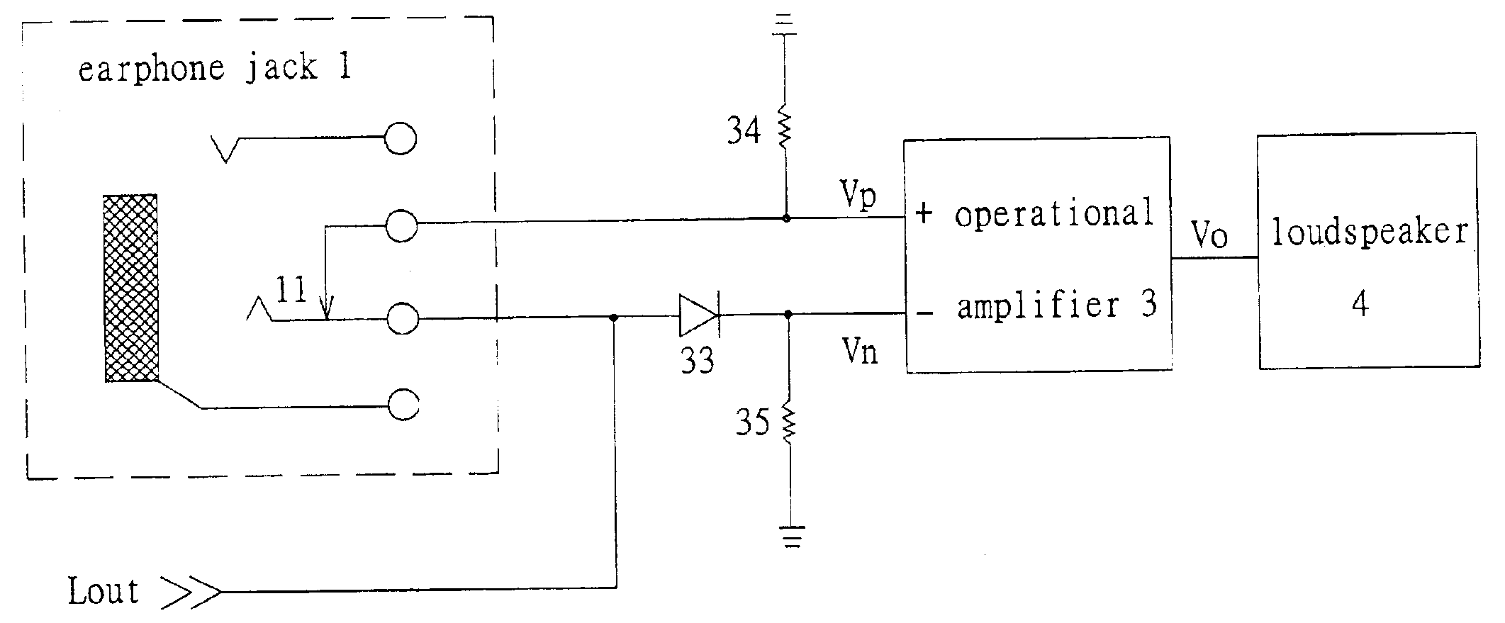
Figure 1 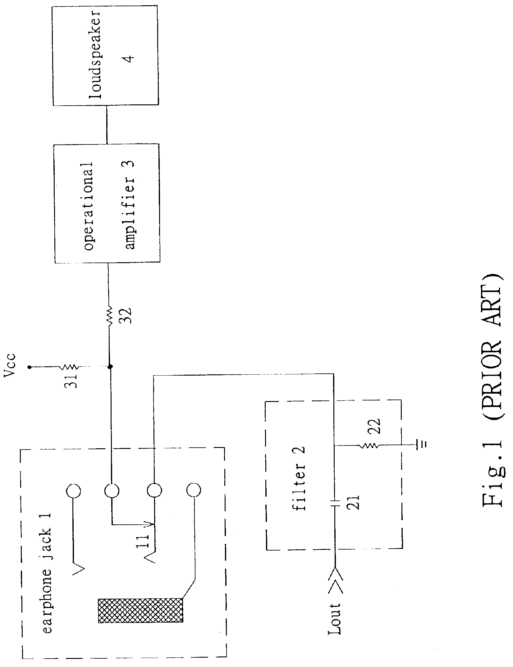
Figure 2 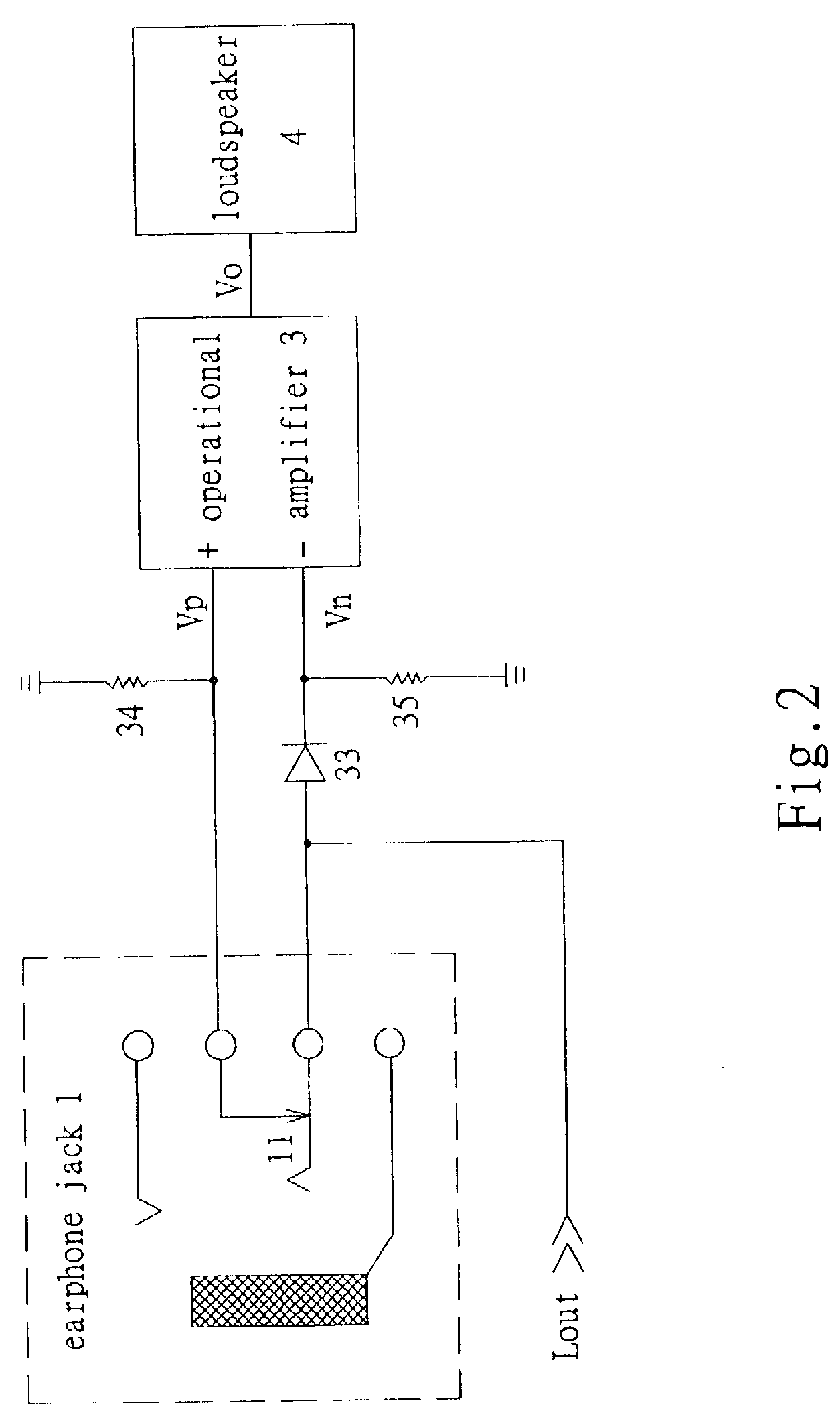
Figure 3
Abstract
Description
FIELD OF THE INVENTION
[0001] The present invention relates to a switching circuit built in IC for earphone and loudspeaker of portable information device, and more particularly to a switching circuit with the passive components thereof to be built in IC entirely.BACKGROUND OF THE INVENTION
[0002] Conventional switching circuit for earphone and loudspeaker of portable information device is shown in FIG. 1. When a ear phone plug is not inserted into the ear phone jack 1, the audio output Lout is passed through the filter 2 and the switch 11 in the ear phone jack 1 to be fed into the operational amplifier 3 for operating the loudspeaker 4. When the ear phone plug is inserted into the ear phone jack 1 to open the switch 11, the audio output Lout is not fed to the loudspeaker 4, but instead to an earphone.
[0003] The operational amplifier 3 is designed into an integrated circuit, while the capacitor 21, the resistor 22 in filter 2 and the input bias resistors 31, 32 of the operational amplifi...
Examples
Embodiment Construction
[0010]Referring to FIG. 2, the switching circuit built in IC for earphone and loudspeaker of portable information device according to the present invention has no any passive component to be built outside the IC, except the earphone jack 1 and the loudspeaker 4, all other circuits is designed with the operational amplifier 3 to form an IC.
[0011]A diode 33, two input bias resistors 34, 35 are designed into the present invention, as shown in FIG. 2.
[0012]When a earphone plug is not inserted into the earphone jack 1, the audio output Lout is passed through a switch 11 in the earphone jack 1 to be fed to the positive terminal Vp of the operational amplifier 3, the audio output Lout is also passed through the diode 33 to be fed to the negative terminal Vn of the operational amplifier 3. Since the diode 33 has a voltage drop of 0.7 volt, the voltage of the positive terminal Vp of the operational amplifier 3 is higher than that of the negative terminal Vn, thus the output voltage Vo of the...