
Wireless parallel test system and test method based on ZigBee
A test system and test method technology, applied in the field of testing, can solve the problems of large amount of field wiring construction and low test efficiency, etc.
Patent Information
- Authority / Receiving Office
- CN · China
- Current Assignee / Owner
- Publication Date
- 2010-07-21
- Estimated Expiration
- Not applicable · inactive patent
Smart Images
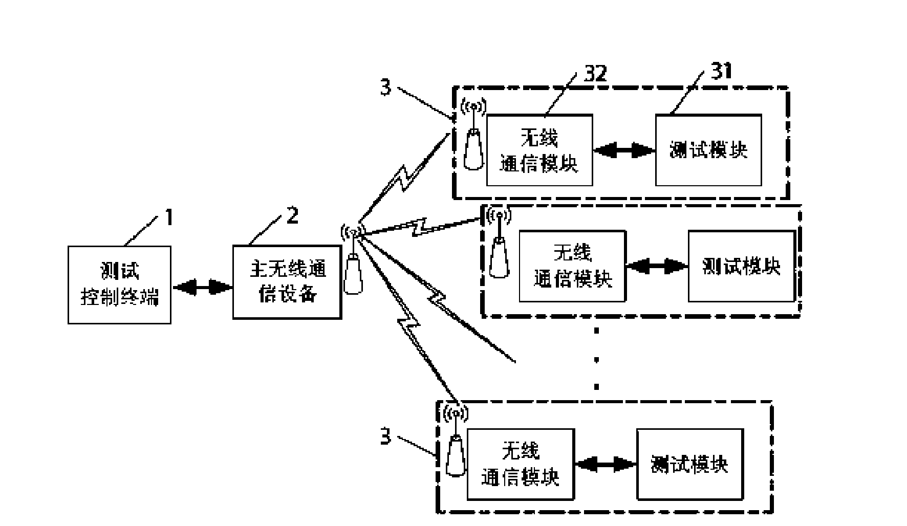
Figure 1 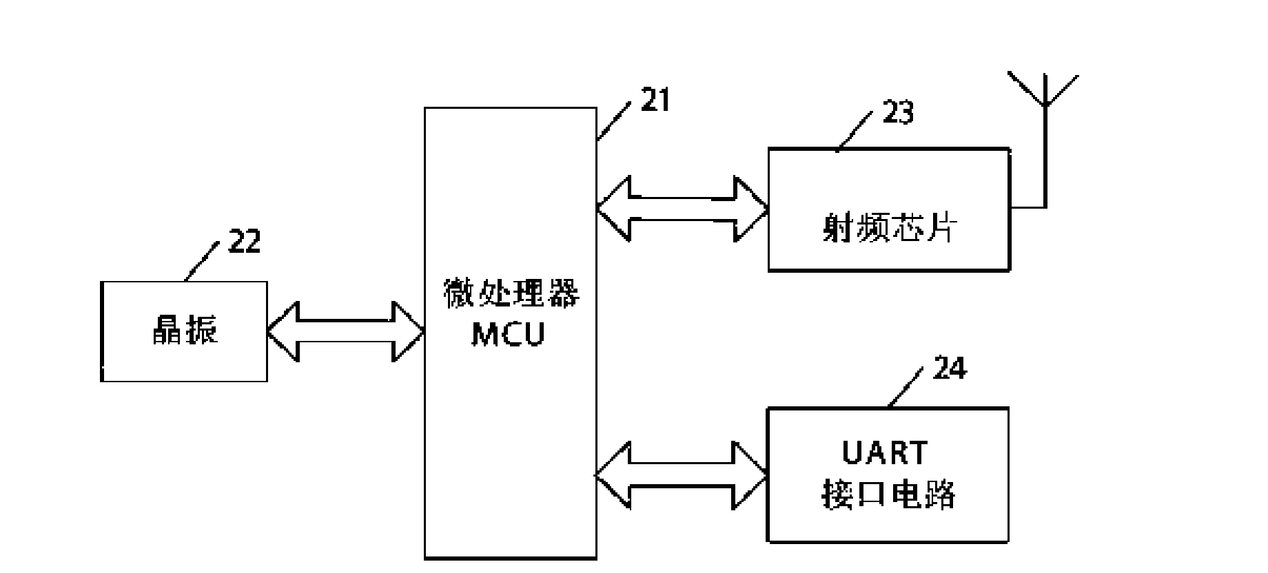
Figure 2 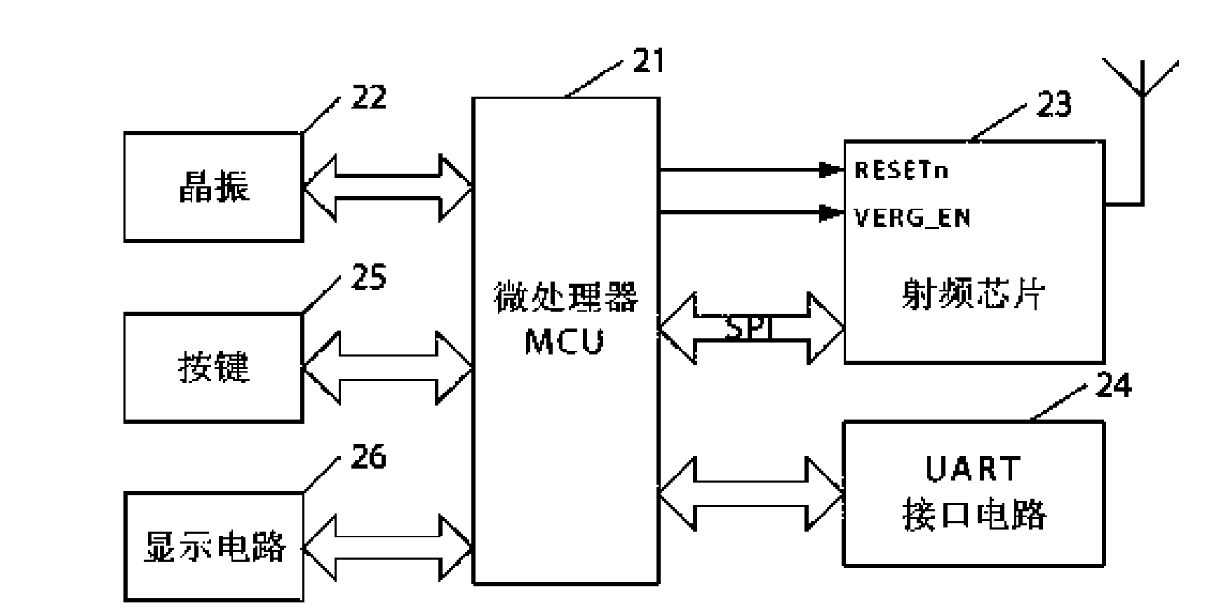
Figure 3
Abstract
Description
technical field
[0001] The invention relates to the technical field of testing, and relates to a testing system and method based on a wireless network.
[0002] A wireless parallel test system based on ZigBee technology can test multiple same DUTs with low cost and high efficiency. It is also widely applicable to wireless testing of various testing equipment in the field of modern automatic testing. technical background
[0003] In the field of instrument testing, a modern automatic test system (ATS, automated test system) integrates multiple devices under test to form a networked test center. In such a test system, communication between various devices is an impact test An important factor of system performance, the traditional test system is generally composed of a wired network, the wiring is complex, the cost is high, and because only one device under test can be tested at a time, the test efficiency is very low. There are many faults in use and are not easy to get rid...
Examples
specific Embodiment approach 1
[0018] Specific implementation mode one: see figure 1 This embodiment will be described. The wireless parallel test system based on ZigBee described in the present embodiment is made up of multiple equipment under test (DUT, Device Under Test) 3, a main wireless communication equipment 2 and test control terminal 1, and there is one in each equipment under test 3 Built-in test module (BIT, buit-in test) 31 and a wireless communication module 32, described built-in test module 31 is connected with described wireless communication module 32 by UART interface, the wireless communication module in a plurality of equipment under test 3 32 and the main wireless communication device 2 form a ZigBee wireless network, and the test control terminal 1 is connected with the main wireless communication device 2 through a UART interface.
[0019] The test control terminal 1 described in this embodiment can be implemented by a PC or a PDA.
[0020] The master wireless communication device ...
specific Embodiment approach 2
[0069] Embodiment 2: This embodiment is a further description of Embodiment 1. The difference between this embodiment and the ZigBee-based wireless parallel test system described in Embodiment 1 is that the structure of the wireless communication module 32 in the main wireless communication device 2 and each device under test 3 is the same, and both adopt microprocessor Device and ZigBee-specific radio frequency communication chip implementation.
specific Embodiment approach 3
[0070] Specific implementation mode three: see figure 2 This embodiment will be described. This embodiment is a further description of the specific structures of the master wireless communication device and the wireless communication modules in each device under test 3 described in the second embodiment. The main wireless communication device 2 described in this embodiment includes a microprocessor MCU21, a crystal oscillator 22, a radio frequency chip 23 and a UART interface circuit 24, and the pulse signal output end of the crystal oscillator 22 is connected to the clock signal input end of the microprocessor MCU21, so The microprocessor MCU21 is connected with the radio frequency chip 23 through the SPI serial communication port, the wireless communication module control I / O port of the microprocessor MCU21 is connected to the control I / O port of the radio frequency chip 23, and the UART interface circuit 24 The serial data input / output port is connected with the serial d...