
Self-locking device for off-circuit tap-changer hand operation mechanism
A technology of tap changer and operating mechanism, which is applied to electric switches, transformers, electrical components, etc., can solve the problems of complex structure and difficult assembly of self-locking mechanism, and achieve the effect of simple structure, prevention of equipment damage and complete functions.
Patent Information
- Authority / Receiving Office
- CN · China
- Patent Type
- Patents(China)
- Current Assignee / Owner
- Publication Date
- 2013-04-03
Smart Images
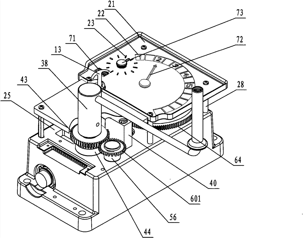
Figure 1 
Figure 2 
Figure 3
Abstract
Description
technical field
[0001] The invention relates to a safety device on an operating mechanism of a tap changer of a transformer, in particular to a self-locking device of a manual operating mechanism of an off-excitation tap changer. Background technique
[0002] In the field of power transmission and transformation, off-excitation tap-changers have been widely used as control equipment for power transformers, such as strip tap-changers and cage tap-changers, which control the moving contacts and static contacts through horizontal movement and rotational movement respectively. The contacts are connected in different ways, thereby changing the number of turns of the transformer coil and adjusting the voltage. The above two tap changers adjust the voltage through the rotation of the rotary shaft.
[0003] Chinese patent application No. 201010271414.X "Manual operating device for non-excitation tap changer" provides a kind of eye-catching display, intuitive reading, complete funct...
Examples
Embodiment Construction
[0016] Embodiments of the present invention will be further described below in conjunction with the accompanying drawings.
[0017] The lower end of the input shaft 36 has a worm screw 36-1, the upper end surface has an arc-shaped groove, the lower end of the handle 38 is a through hole, and the handle 38 is embedded in the arc-shaped groove on the upper end surface of the input shaft 36 with a pin 38-1 to form a whole. , the input shaft is connected on the base 25 and the bottom plate 27 through bearings.
[0018] The intermediate shaft 56 is connected with the upper and lower intermediate gears 601 and 602 with collars respectively, and is fixed on the base 25 through bearings, the transition shaft 57 is fixed on the base 25 through bearings, and the transition gear 603 connected at the end is connected to the lower intermediate gear. 602 meshes, and the upper intermediate gear 601 meshes with the self-locking gear 43 on the input shaft 36, as Figure 7 , Figure 8 , Fig...