
A kind of rescue stone throwing machine
A technology of riprap machine and engine, which is applied in the field of emergency riprap machines, can solve the problems of low emergency rescue efficiency, achieve the effects of avoiding huge loss, reducing huge waste of emergency materials, and easy road transportation
Patent Information
- Authority / Receiving Office
- CN · China
- Patent Type
- Applications(China)
- Current Assignee / Owner
- Publication Date
- 2011-12-28
- Estimated Expiration
- Not applicable · inactive patent
Smart Images
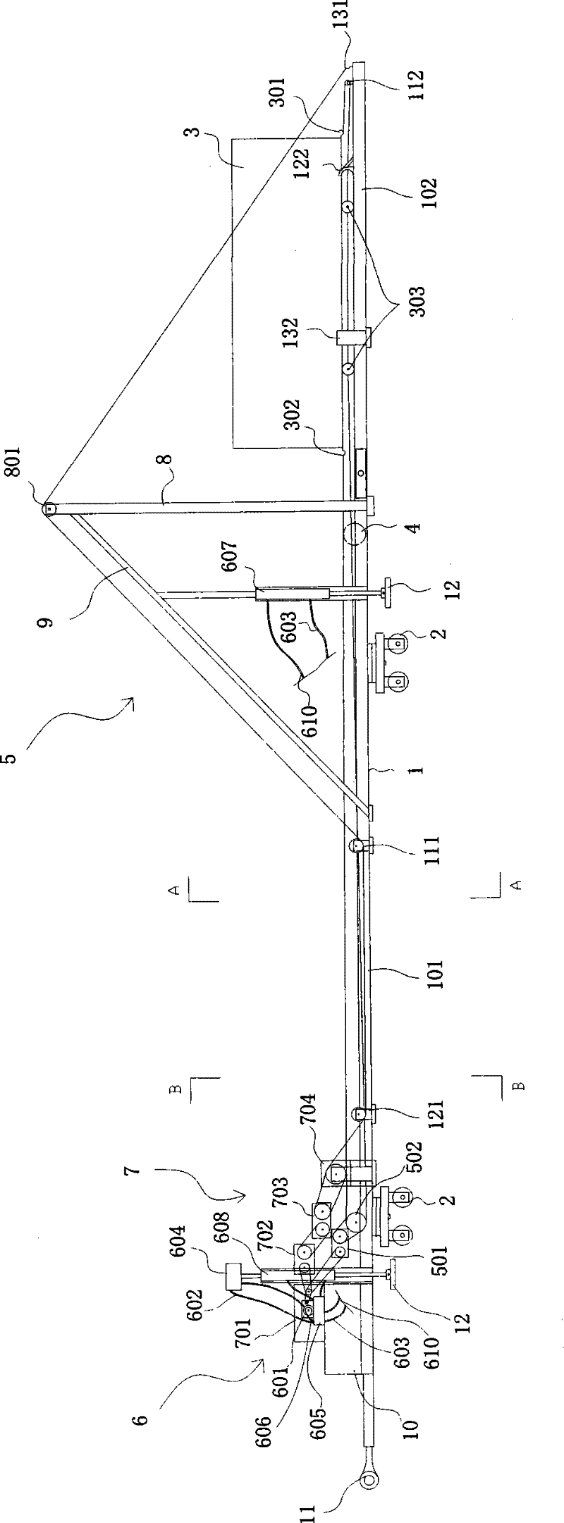
Figure 1 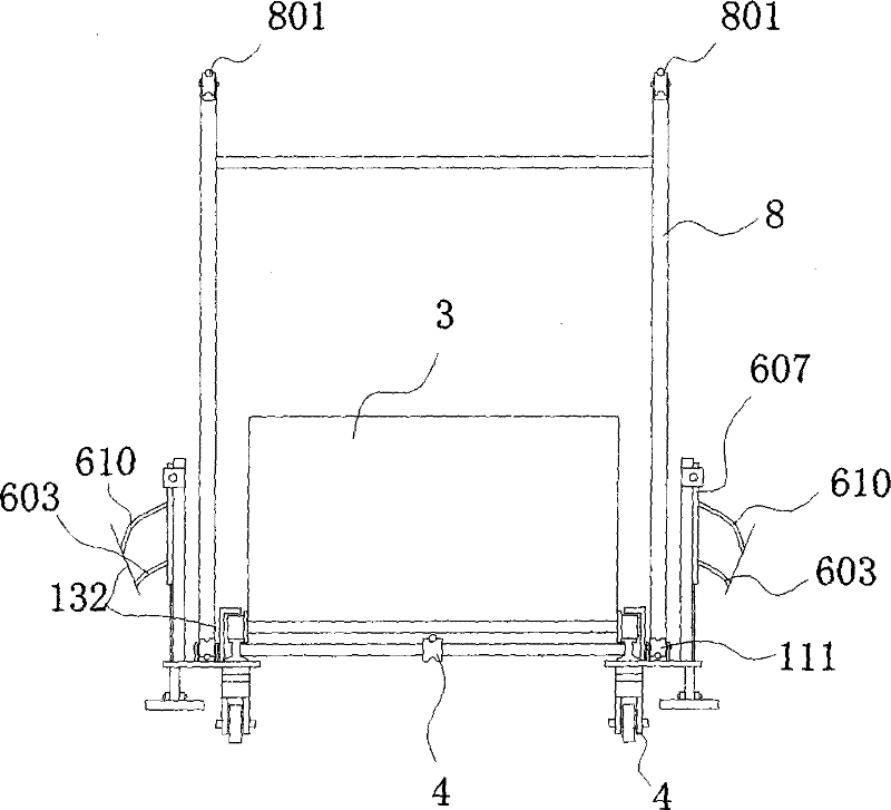
Figure 2 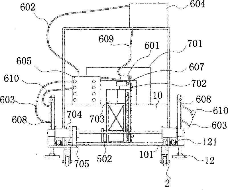
Figure 3
Abstract
Description
technical field
[0001] The invention relates to a mechanical device for emergency riprap, in particular to an emergency riprap machine. Background technique
[0002] At present, the structure of the known emergency trebuchet is a tool assembled by chute, feed inlet, landing gear, and walking parts, and no power unit is installed. Generally, the loose stones or smaller throwing objects to be thrown are loaded from the feed port through other machines, and the materials slide down the chute to the emergency position through their own weight, that is, in this way. The whole process of the whole rock-ripening rescue operation. However, such emergency trebuchets can only throw loose stones or small soil bags. Because the flow rate of water in the emergency position is generally very large during the rescue process, the smaller objects thrown are easily washed away by the rapids. , so that it is difficult for the thrown material to stay at the root of the emergency and be washed...
Examples
Embodiment Construction
[0031] The present invention will be further described below in conjunction with accompanying drawing:
[0032] The emergency stone throwing machine provided by the present invention comprises a track 1, a track wheel 2 arranged at the bottom of the track 1, a feeding hopper 3 arranged at the top of the track 1, and a middle wheel 4 arranged at the middle of the connecting rod at the front end of the fixed track. The machine also includes a feeding system 5, a hydraulic system 6, and a transmission system 7 for controlling the feeding system 5 and the hydraulic system 6.
[0033] The transmission system 7 includes an engine 701, a first gearbox 702 driven by the engine 701 through a pulley, and a moving rail hoist 704 driven by a chain through the output chain wheel on the reducer 703 driven by the gearbox 702 through a pulley;
[0034] The hydraulic system includes a hydraulic pump 601 driven by an engine 701, a hydraulic pump oil tank 604 that supplies hydraulic oil to the h...