

Traction sleeper device
A technology for pulling pillows and bolsters, which is used in transportation and packaging, transportation of passenger cars, tankers, etc., can solve the problems of stress concentration and low reliability of side tube struts, and achieves reduction of stress concentration level, increase of wrap angle, and increase of diameter. Effect
Patent Information
- Authority / Receiving Office
- CN · China
- Current Assignee / Owner
- Publication Date
- 2012-06-06
- Estimated Expiration
- Not applicable · inactive patent
Smart Images
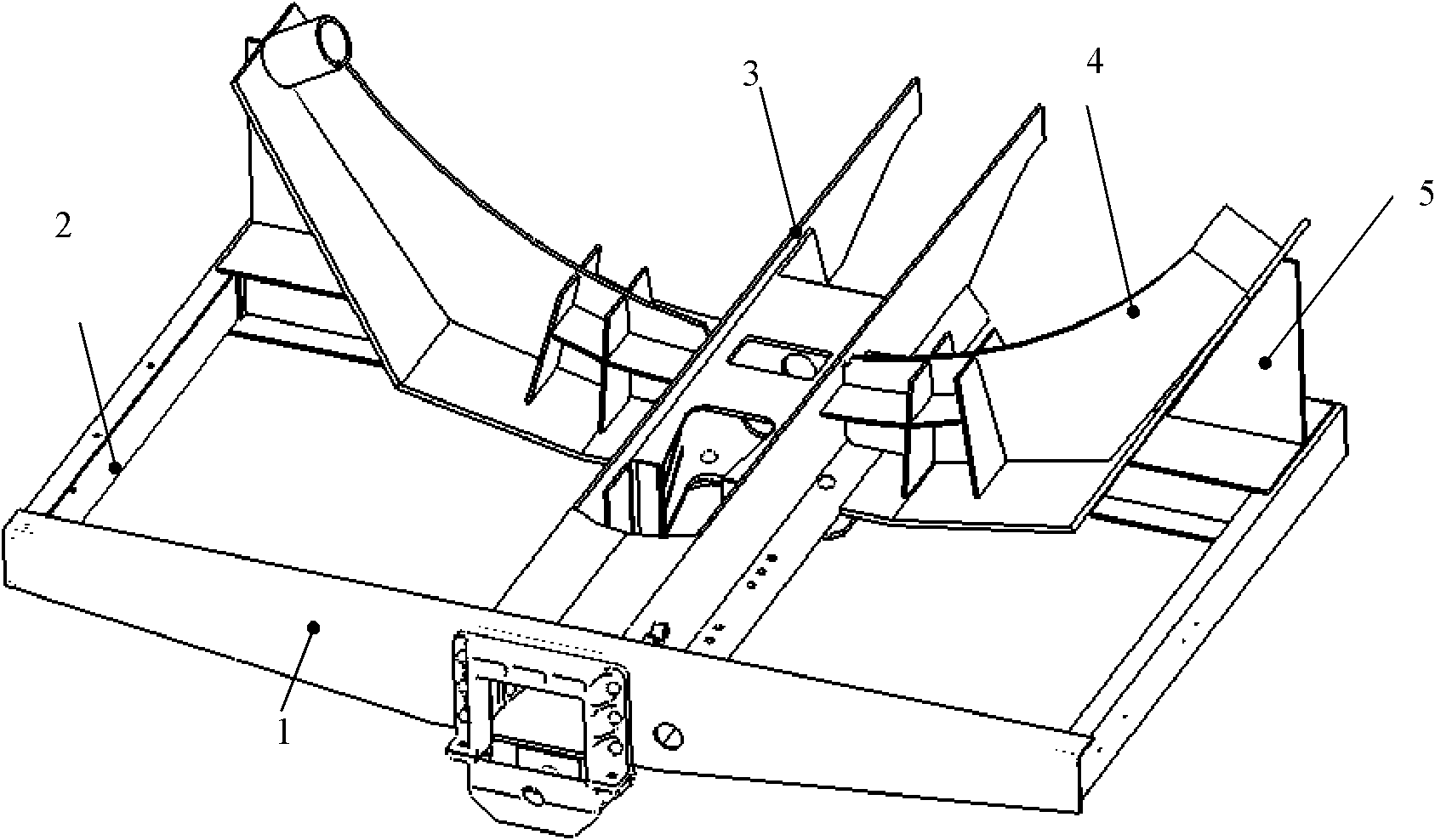
Figure 1 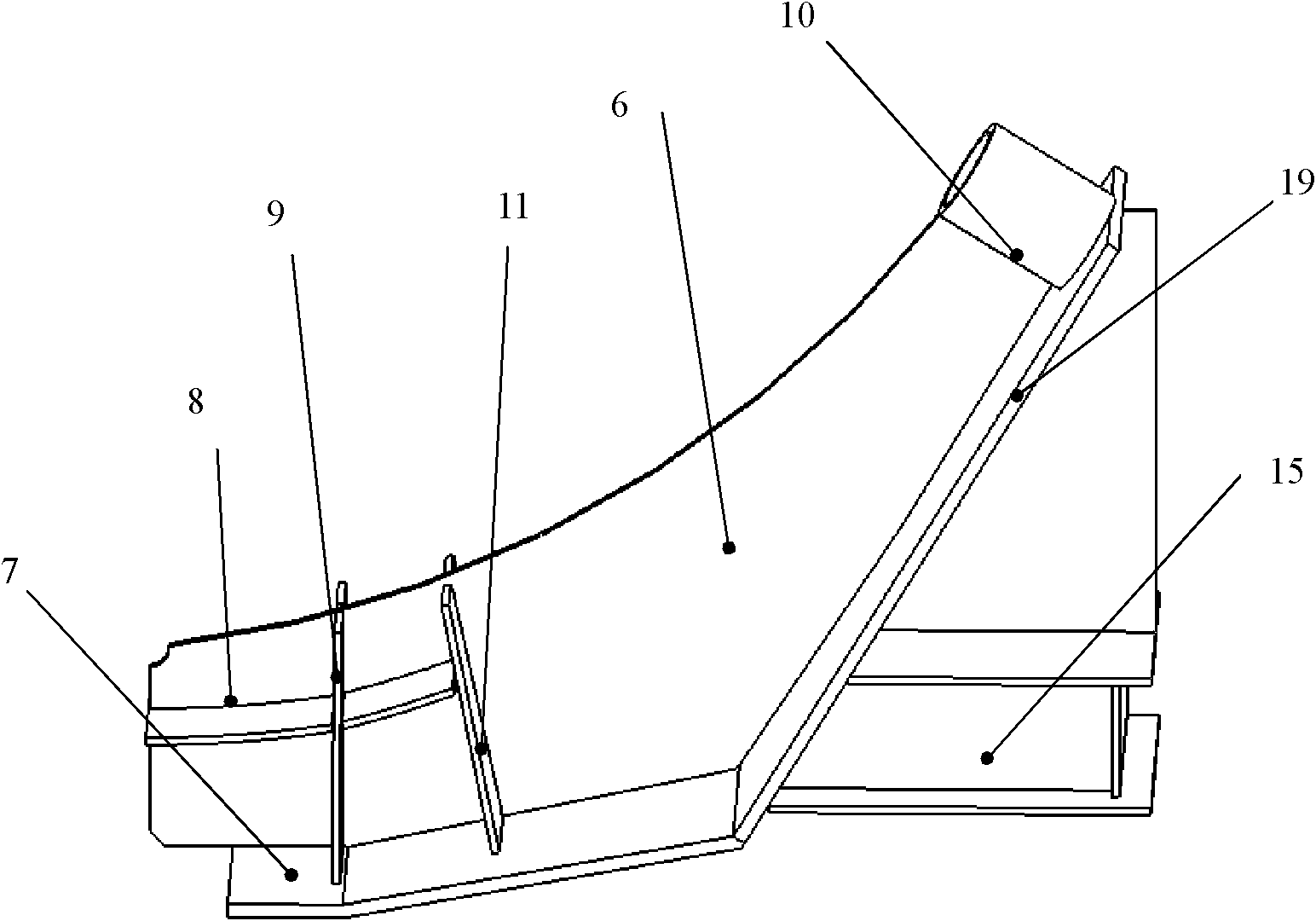
Figure 2 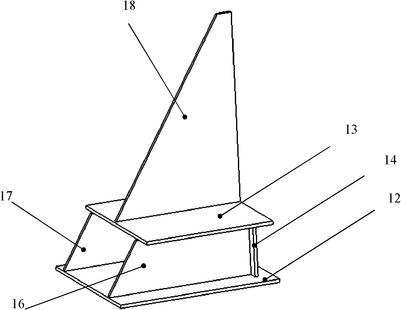
Figure 3
Abstract
Description
Technical field
[0001] The invention relates to a pillow holding device of a tank car. Background technique
[0002] At present, the railroad tank car in my country is widely used in the traction sleeper structure without center beam. The transmission path of the longitudinal load on the single tank car is: one end coupler-sleeper device-lower part of the tank-the other end sleeper device-the other end coupler . While transmitting the longitudinal load between the vehicles, the pillow device also supports the tank and bears the vertical load. Take the 70-ton-class railway tank car as an example. In my country's railway freight car assessment standards, the maximum longitudinal load is 250 tons, and the vertical static load is 70 tons. At the same time, it must bear the effects of saturated vapor pressure and liquid shock pressure. bad.
[0003] The harsh working conditions have brought a greater impact on the force of the traction device, and there are mainly the following two pro...
Examples
Embodiment Construction
[0025] See figure 1 , The preferred embodiment of a pillow-traction device involved in the present invention is:
[0026] The device mainly includes an end beam 1, a side beam 2, a traction beam 3, and a corbel 4; the side beam 2 is vertically connected to both ends of the end beam 1; the traction beam 3 is vertically arranged in the middle of the end beam 1; the corbel 4 is symmetric It is arranged on both sides of the traction beam 3, and its other end is connected with the other end of the side beam 2. The end beam 1, the side beam 2, and the traction beam 3 can all adopt the structure in the prior art; the corbel 4 of the present invention includes a web The plate 6, the lower cover plate 7 arranged under the web 6 and the stiffener plate; the stiffener plate can be arranged vertically on the web 6, which can reduce the longitudinal and vertical load at the connection between the web 6 and the traction beam 3 Stress under working conditions.
[0027] The stiffener plate of the...